|
Node and sectional node point designation |
Scroll |
In KOMPAS-3D you can create:
•designation of a node point in section.
For precise cursor positioning and parameter setting during the construction process, you can use Snaps and geometrical calculator.
To create a node point designation, use the Node point symbol  command.

Step-by-step instructions
1.Set the center of the contours limiting the node.
The phantom of designation of a node will appear in the graphic area.
2.Set the parameters of designation of a node. That is done the same way as on creation of leader element designation for mechanical engineering. Details...
3.Indicate a point on the contour of designation or set the contour dimensions in the respective fields on the Parameter Panel.
|
If the node point designation contour is shaped as a rectangle or a rounded rectangle, its sides are parallel to the axes of the view's coordinate system, regardless of the current LCS. |

4.The number suggested by the system is displayed in the Text field on the Parameter Panel and on the designation phantom in the graphic region. If necessary, change the caption and/or its typeface. Details...
5.If after labeling a designation of node the view associated with it, include the option Create View.
6.Specify the starting point for the landing. After you indicate this point, creation of leader element designation ends automatically.
7.To complete operation of the command, click Finish  .
.
|
|
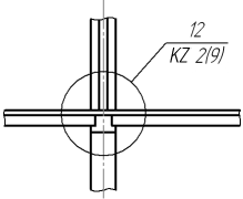
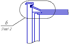
Examples of designations of nodes
On labeling a node, auto create hyperlink, linking the designation to the newly created view.
Sectional node point designation
The Sectional node point symbol  command is used to create a node designation in the section.
Step-by-step instructions
1.Specify the hatch snap point. Snap point is the mid point of a hatch.
In the graphic region, a designation phantom will appear.
2.Set the hatch length in the Dash lengthfield on the Parameter Panel.
3.Specify the starting point for the landing. The slope angle of a hatch will be automatically determined, its value will be displayed in the Angle field.
If it is necessary to set a certain slope angle of a hatch, enter its value in the Angle field. Then specify a point of origin of the landing.
4.Add the required number of hatches, specifying the position of mid points. If hatches should have different lengths, enter the length of each subsequent hatch in the Dash length field.
5.If it is required to edit designation, switch to the Edit Points mode. In this mode you can change an arrangement of hatch and the landing and to delete hatches.
To continue adding hatches, return to the mode of Adding hatches.
6.Set the direction of the landing by pressing the required button in the Leader Landing group:
 To the right,
 To the left,
 Up,
Up,
 Move Down.
The direction of landing can also be changed by scrolling the mouse wheel with the <Ctrl> key pressed. In so doing, switching between the options of landing placement is performed.
7.The node point number offered by system is displayed in the Text field on the Parameter Panel and on the designation phantom in the graphic region. If necessary, change the caption and/or its typeface. For that, click in the Text field or in a text box on the phantom, or press any of the alphanumeric keys on the keyboard. The Add Text subprocess will be started. Details...
8.If after labeling a designation of node in section, the view associated with it, Enable the option Create View.
9.To complete creation of the designation, click Create Object  button.
10.To complete operation of the command, click Finish .
|
|
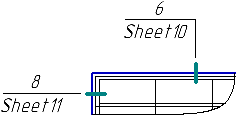
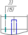
Examples of designations of units in section
On labeling a node in section, automatically create hyperlink, linking the designation to the newly created view.
|
The styles of hatch lines and lines between the hatches, as well as enabling the option of drawing a line between the hatches are determined by the settings made in the section Node and Node in Section — General Settings, while the default length of the hatch and the gap between the hatch and the leader line are determined in the section Node and Node in Section — Parameters dialog for the current document settings. |