|
Plotting along axes |
Scroll |
You can plot a point of a 3D spline or broken line in such a way as to construction line is positioned parallel to one of the axes of coordinate systems of curve.
You can select an axis as follows:
•click the button corresponding to the required axis ( ,
,  or
or  ), in the group of buttons Method on the Parameters panel,
•select the axis using the phantom of the coordinate axes. This phantom is displayed near the previous point of the curve in the graphic area of the model.
|
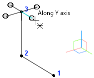
Setting a coordinate axis in the graphic area of the model
When you press a button in the Method group, the phantom in the graphic area will automatically change; when you select an axis in the graphic area, the buttons in the Method group are toggled.
After a coordinate axis is selected, a point plotting line parallel to this axis will be displayed if you move the mouse pointer in the graphic area.
You can set the position of the point on the plotting line as follows:
•setting the offset of the created point relative to the previous point or the base surface.,
•setting the position of the point in the graphic area (the coordinates of the point coincide with the projection of the mouse pointer to the plotting line),
•selecting a Point Object — in this case, the curve point will coincide with the projection of the indicated point object on the point plotting line, and the value of the coordinate along the selected axis will be equal to the value of this coordinate at the indicated point object.
After you specify the position of the point using one of the aforementioned methods, a new point of the spline (broken line) appears in the graphic area, and its parameters appear in the Point parameters table.
There are two ways to set the offset along the selected axis:
•from the previous point of the curve,
•from the base surface.
Displacement from the previous point of the curve
This way, you can set the offset of the new curve point from the previous point along the plotting line (the distance between these two points).
To set the offset, please to the following.
1.Press the From previous point  button in the Move button group in the Vertex Design group.
2.In the Distance field, enter offset value. The sign in front of the value defines the location of the new point: in front of the previous point or behind it.
Displacement from the base surface
Using this method, you can set the offset of the point from the base surface (face or plane). The position of the new point is set as follows.
1.A new surface is plotted. This new surface is equidistant to the base surface, and the distance between the equidistant surface and the base surface equals the offset value.
2.An intersection point of the plotting line and the equidistant surface is located.
The theoretical surface of the face is extended if needed (to learn about a theoretical surface of a face, see section Parametric representation of the surface. Isoparametric curves Add-Ons Curves and Surfaces).
3.The new point is superposed with the resulting intersection point.
|
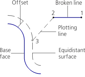
Defining the position of a point by setting its offset from the base face.
To set the offset, please to the following.
1.Press the From Reference Plane  button in the Move button group of the Vertex Design group.
2.Select the face or plane in the graphic area of the model. You can also define the plane in the Design Tree. The selected object is highlighted, its name is displayed in the Base surface field.
3.In the Distance field, enter offset value. The sign in front of the value defines the location of the new point: in front of the selected face (plane) or behind it.