|
Names and icons of objects in the Design Tree |
Scroll |
Names of objects in the Tree
Names of objects that have properties, such as the root object of the Tree, components, and bodies, are composed of the values of these properties; arbitrary characters, or prefixes, may precede the property values.
For example, let's consider the component name «ABVG.001.000. M=50». It includes values of properties Designation — ABVG.001.000 and Mass — 50. Before the value of the property Mass a prefix «M=» is inserted. The properties included in the name and their sequence are defined in the dialog of the name format configuration in the Document Tree. By default object names consist of the designation and name. If the values of the object properties included in the name are not defined, then the name will be assigned according to the object type (Part, Assembly, Solid).
Names of other objects in the Tree are assigned automatically depending on the method used for their generation. For example: Rotational element, Axis through the edge, Chamfer, Coaxiality (Cover – Gasket), etc.
You can rename an object directly in the Tree by pressing the <F2> key. Besides, objects can be renamed using the Parameters Panel or in the process of editing properties. Please note the following when renaming:
•Certain objects, e.g. matings, do not support renaming.
•Object name composed of its properties can be edited in the Tree by pressing the <F2> key only if the name includes the property Name. This will change the value of this property only, but not the values of other properties included in the name.
•The default properties of assembly components are linked to the properties of the corresponding models in the component source files. Renaming a component in the assembly will break this link for the property Name, resulting in the source name changes no longer being transferred to the assembly. To restore the link (and restore the source name of the component), you will need to edit properties of the component.
An icon is displayed to the left of the name of each object in the Tree. Unlike the name of the object, you cannot change the icon. Due to this, when you rename any objects, visual information about the method of their creation is retained in the Design Tree.
Icons in the Design Tree are usually displayed in dark gray. If the object is specified for the execution of the operation, its icon in the Tree becomes red. If the object is hidden or excluded from calculation, its icon and name will be light grey.
The list of icons of components and solids can be found in the table of Interface elements Appendix.
Signs showing the status of the object may appear between the icon and the name of the object. For example, a component may have a restriction attribute on editing, fixation, etc. After the object's state changes, the icon disappears or is replaced with another.
For example, in figure a), the Switch component is fixed — indicated by the  icon next to its symbol, while the Key component is fully defined by mates — indicated by the
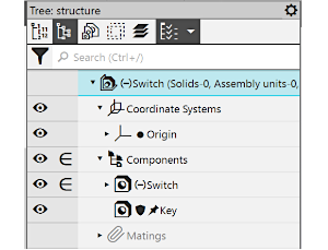
  icon. In figure (b), the fixation of the component Switch is canceled (the icon disappears), indicating that this component is not fully defined, as shown by the
  icon; the
  and icons next to the icon of the Key component indicate the prohibition of editing and the fixation of this component.
|
|
a) |
b) |
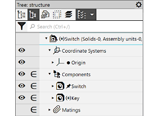
Model Tree icons
a) the Switch component is fixed, the Key component is fully defined;
b) the Switch component is not fixed and not defined,
The Key component is not available for editing and is fixed.
The list of additional designations is shown in table Icons in the Document Tree of Interface elements Appendix.