|
Bend Placement |
Scroll |
Placement defines the bend position in the plane of the base face relative to the bend base line. The bend placement controls are available in the Bend, Bend by Line and Incision.
In the Bend command, the placement method is selected using the Method group of buttons located in the Bend Placement group of elements.
In the Bend by Line and Incision commands, the placement method is selected using the Location group of buttons.
The following bend placement methods are available:
 Offset inside (this option is available in the Bend command),
 Offset outside (this option is available in the Bend command),
 By transition line (this option is available in the Bend by Line and Incision commands),
 By outer contour line,
 By inner contour line,
 By tangency,
 By bend line.
Bend placement methods are described below.
Offset Inside or Outside
Practices Move Inward and Move Outward are available in the Bend command.
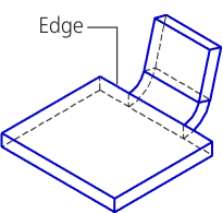
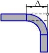
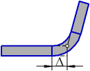
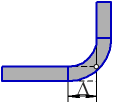
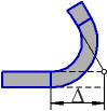
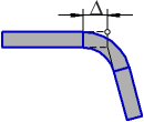
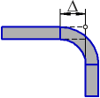
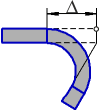
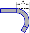
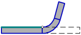
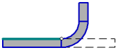
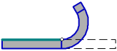
Offset defines the shift of the bend in the plane of the base face perpendicular to the edge on which it is located.
The offset value is entered in the Move field. The zero value in this field means that the bend starts directly from the edge.
|
|
|
a) |
b) |
c) |
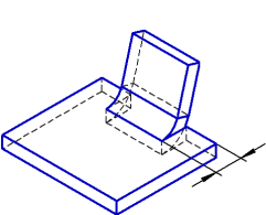
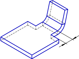
Bend offset: a) zero, b) inward, c) outward.
Placement by transition lines, by outer or inner contour line, by tangency
The Transition Lines method is available in the Bend by Line and Incision commands.
The principles of bend placement methods: By external contour line , By internal contour line , and By tangency differ in the Bend command and in the commands Bend by line and Incision.
Methods of the bend placement and their results in different commands of bend construction are given in the Tables.
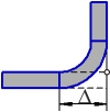
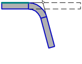
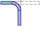
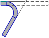
Schemes of bend construction in the Bend command depending on the placement method
(the schemes show the model projection onto the plane perpendicular to the edge along which the bend is located; the edge projection is marked with a circle)
Placement method |
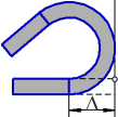
Bend angle from 0° to 90° |
Bend angle 90° |
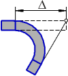
Bend angle from 90° to 180° |
Bend angle greater than 180° |
|
|
Along the outer contour line |
|
|
|
|
|
|
|
|
||
|
Along the inner contour line |
|
|
|
|
|
|
|
|
||
|
By tangency |
|
|
|
|
|
|
|
|


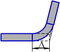

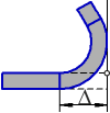

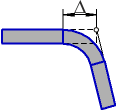
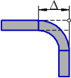

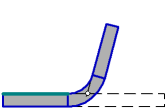
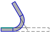
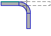
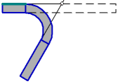
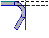
Bend drawing schemes in the Bend by Line and Incision commands based on the placement method
(the schemes show the part projection onto a plane perpendicular to the base line of the bend; the projection of the base face is marked with a thick segment and the projection of the base line of the bend is marked with a circle)
Placement method |
Bend angle from 0° to 90° |
Bend angle 90° |
Bend angle greater than 90° |
|
|
By transition line |
|
|
|
|
|
|
||
|
Along the outer contour line |
|
|
|
|
|
|
||
|
Along the inner contour line |
|
|
|
|
|
|
||
|
By tangency |
|
|
|
|
|
|


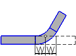
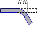
The placement method By bend line means such a bend offset relative to the bend base line, where the base line will be in the middle of the flat patterned cylindrical part of the bend in the flat pattern of a sheet part.
Bend offset relative to the bend base line on the flat pattern is calculated according to a formula which depends on the selected method to determine the flat pattern length:
W = (π · α (R + K · S))/360 – when using the method Coefficient,
W = BA/2, using the Bend amount,
W = (R + S) · tg(α/2) – BD — when using the method Bend Reduction,
where
W is bend offset relative to the bend base line,
α is the bend angle,
R is the internal bend radius,
S is the thickness of sheet material,
K is the position coefficient of the neutral layer,
BA is the flat pattern length of the cylindrical portion of the bend,
BD is the bend reduction.
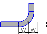
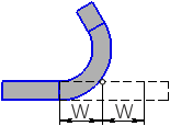
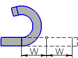
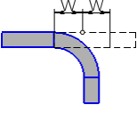
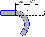
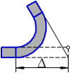
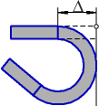
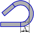
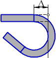
The results of placement using the By Bend Line method for different bend angles are given in the Table. The scheme shows the part projection onto the plane that is perpendicular to the bend base line. The projection of the bend base line is marked with a circle.
Bend detailing using the By Bend Line method
α<90° |
α=90° |
90°<α<180° |
α > 180° |
|
|
|
|
|
|
|
|
|
|