|
Geometric Tolerance |
Scroll |
To create a designation of geometric tolerance and placement, use the Geometric Tolerance command  .
.

Step-by-step instructions
1.Specify an object to set the geometric tolerance designation. The name of selected object is displayed in the Objects field on the Parameter Panel. In the graphic area, a phantom of the tolerance table will appear.
2.Specify the location of the tolerance marquee.
3.After indication of the marquee position, the Add Text subprocess will be launched. Generate a tolerance table. That is done the same way as when creating a designation of geometric tolerance and surface placement in the graphic document. Details...
4.After indication of the designated object, the position of the plane of designation is determined automatically. By default, one of the coordinate planes is used as the base plane.
You can change the designation plane using the controls of the Location group.
5.The left bottom corner of the tolerance marquee coincides with the point determining the position of designation. If you want to change the position of the marquee relative to the insertion point, activate the corresponding point of the Position element on the Parameter Panel.
6.The tolerance marquee is placed horizontally. If you want to place the marquee vertically, enable the Vertically option.
On the phantom of the marquee, eight characteristic points showing possible places of outlet of branches are displayed. Create the necessary number of branches of the leader line. Details...
Each new branch is created with an arrow. You can change the arrow type by means of the context menu of the defining point at the end of the branch.
7.If necessary, set the name and color of the designation using the controls in the Properties section. More details on managing object colors...
8.To complete creation of a geometric tolerance designation, click Create Object button  .
.
After completing the described actions, a geometric tolerance designation will appear in the graphic area and its icon will appear in the Design Tree.
9.To complete operation of the command, click Finish  .
.
|
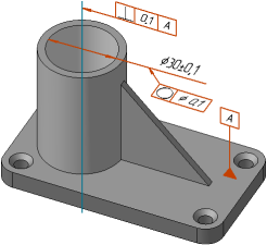
Example of setting a geometric tolerance and surface positioning
See Also