|
Collision check |
Scroll |
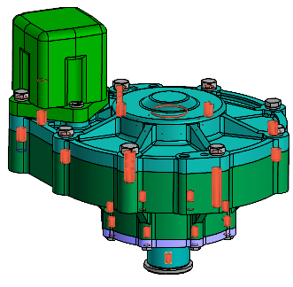
Checking of collisions in a model can determine intersections, tangencies and gaps. Collisions can be checked both between separate objects of a model (components, solids) and between sets. Sets are groups of objects arbitrarily formed by the user. A set may, for example, include separate components of an assembly.
•If sets are selected for checking, intersections/tangencies and gaps between groups of objects (but not within groups) can be found.
•If components are selected for checking, intersections/tangencies and gaps between the solids belonging to these components (but not between the solids belonging to one component) can be found.
•If solids are selected for checking, intersections/tangencies and gaps between them can be found.
The collisions found are displayed in the graphic area.
|
|
a) |
b) |
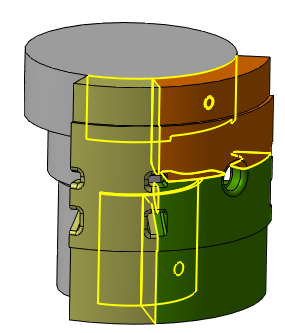
Examples of collisions in a model: a) Intersection, b) tangency
The Collision check  command is used for checking of collisions.

Step-by-step instructions
1.Select the checking option in the Method field on the Parameters Panel:
•Between selected objects each of the selected objects is checked for collisions with all other selected objects.
Specify the objects to be checked for collisions. Object names are displayed in the Objects field.
|
When you select a subassembly, note that you may check or not check its components for collisions between them. For this, the option Subassembly as a single object is used. •If the option is enabled, checking of collisions between components of the selected subassembly is not performed. •If the option is disabled, checking of collisions between components of the selected subassembly is performed. |

•Between two sets of objects: each object in the set is checked for collisions with all objects of the other set.
Activate the Set 1 field on the Parameter Panel and specify the objects included in it. Object names are displayed in the field. Activate the Set 2 field and specify the required objects.
Selecting objects in the Design Tree
Selecting objects in the model graphic area
2.If you want to find objects that have a common line or surface, enable the Handle touches option.
3.If required, check coincidence of thread parameters in a threaded joint. To do this, enable the Machining threads option. More details on checking threaded connections...
4.You may exclude detailing geometry and (or) hidden objects. To do this, enable the relevant option in the Exclude from Validation group. More details on excluding objects from checking...
5.If it is necessary to check the gaps, set the Check Gaps toggle switch to I (enabled). More details on control of gaps...
6.Run Collision check. To do this, click Check Now link in the header of the Results table on the Parameters Panel. You can follow the checking progress using the progress indicator in the graphic area.
The check can be stopped by clicking Cancel on the indicator panel or the Stop link in the Results table header.
Check results are displayed in the table and in the graphic area. More details about the results of checking...
7.In the graphic area, you can leave only one pair of objects between which a collision occurred. For this purpose, enable the Hide surroundings option and select the desired row in the Results table.
8.To save checking for collisions (objects as well as checking parameters will be saved), click Save  in the header of the Parameters Panel. You may enter a name of this check in the Name field of the Properties section.
After the check is saved, an object with a relevant  icon appears in the Design Tree . This action does not deactivate the command. If required, you can change the check parameters. If the check parameters change, the header of the table Results displays a Recalculate link.
9.To complete the collision check command, click Finish  on the Parameter Panel header.