|
Plotting linear surface by curve and direction |
Scroll |
To plot a linear surface using a curve and an object that sets the direction for segment construction in a section, the Linear surface by curve and direction command  is used.

Step-by-step instructions
1.Specify the curve along which the segment-section will move. The starting point of a segment will be located on this curve in any position.
The following can be specified as a curve:
•a spatial curve or, in the case of a contour or a broken line, individual segments,
•sketch line or entire sketch (indicating the entire sketch is possible if it contains one object or one chain of objects),
•edge,
•a chain of the above objects in any combination (objects are specified in their junction order).
|
If a multi-segment curve or a chain of objects linked in a sequence is used, a surface can be created only when tangents in segment junctions cross with angled lower than 60°. |

The name of the selected object(s) is displayed in the field Curve of the Parameters panel.
If you need to move the section segment along the selected curve in reverse direction, click Reverse Direction  button next to the Curve field.
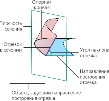
2.Select an object, whose projection on the section plane will determine the direction of displacement of the endpoint of the segment (see. Figure). To do this, activate the field Direction and specify one of the following objects:
•straight-line object — the object itself is projected onto the section plane,
•flat object — a straight line perpendicular to this object is projected to a section plane,
•Construct a vector — the constructed vector is projected onto the section plane.
 located to the right of the
|
It is necessary for surface creation, that the projected object is not parallel to the reference curve. |
The name of the selected object is displayed in the Direction field. A phantom of a linear surface being created with default settings is displayed in the graphic area.
3.Set the angle between the segment-section and its projection on the section plane of the specified reference object (see the previous item). To do this, use the elements of the group Deviation. Select a function type to define the angle and set input values for this function. More details on setting the angle...
Change Direction button next to the field for setting the angle allows changing the construction direction of the segment to the opposite (see figure).
|
|
a) |
b) |
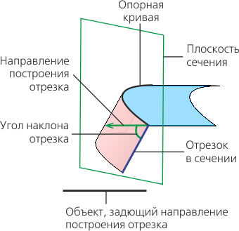
Position of section segment:
a) by default; b) after changing drawing direction.
4.Set the length of the segment-section by defining the displacement of its end point relative to the starting point using the elements of the Move group. Select a type of the function that will be used to determine the offset and set the values for the selected function. More details on setting the length of the segment...
5.Specify an object defining the orientation of the section plane during the movement of the segment. To do this, use controls of the Design section. The type of movement can be selected using the Section Movement. The following options are available:
 Parallel to itself — the segment in each of its positions is in the plane that is perpendicular to the straight-line direction set by the guiding object (Figure a).
 By line — the segment in each of its positions is in the plane perpendicular to the specified guiding line — curve of arbitrary shape (Figure b).
|
|
a) |
b) |

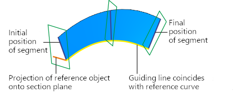
Different types of section segment movement provide different results:
a) parallel to itself, b) along the line
Types of objects used to define the section plane orientation, and the order of their selection are described in the section. Objects Defining Orientation of the Section Plane during the Movement of the Segment-Section.
|
The object to define the section plane orientation should be selected in such a way that this plane intersects with the reference curve. The angle between the section plane and the object used to define the segment position in the section can not be 90°. Otherwise it's impossible to create a linear surface. |
6.To check a surface for self–intersections, please enable the Self-intersection check setting. If any self–intersections are detected, a corresponding message will appear on the screen. More details on surface self-intersection...
7.If necessary, set the name of the created surface and the properties of its display using the controls located in the Properties section. Management of the color and optical properties of objects...
8.To complete the operation, click Create an object  .
.
The created surface will be displayed in the graphic area; its icon .
9.To complete operation of the command, click Finish button  .
.
Tips
You can set linear and angular parameters using the geometrical calculator.
See Also