|
Plotting a linear surface by two surfaces |
Scroll |
To plot a linear surface tangent to two surfaces, use the Linear Surface by Two Surfaces  .
.

Step-by-step instructions
1.Specify reference surfaces — Surface 1 and Surface 2. A section segment of a linear surface will be tangent to both those surfaces – to one in the starting vertex and to the other in the ending vertex.
|
The necessary condition for plotting a linear surface is positioning the surfaces 1 and 2 in such a way that the section plane intersects both surfaces and a segment can be drawn between the resulting intersection curves, which lies in the section plane. |

The surfaces 1 and 2 may be defined based on a non-flat face of a solid or a surface. coherent set of faces of a solid or surface.
You can also select a whole solid or surface. To do that specify the needed object in the Design Tree or select all elements of the needed object using the Marquees. in the graphic area. A linear surface will be plotted through all the faces of the selected solid or surface, which are located within plotting conditions. Later the plotting result will be changing according to changes in faces number.
If necessary, you can specify several non-coherent faces or faces with common edges but belonging to different solids/surfaces. In this case plotting produces not one, but several linear surfaces (according to number of faces satisfying the plotting conditions). After the command finishes, you can select surfaces to keep in the model (see below).
|
It is permissible to have faces, not complying to the plotting conditions, in the list of selected faces. They are simply ignored in the plotting process. If, in the future, the shape and/or position of the faces change such that the construction condition is met, then the resulting ruled surface will also change. |
|
When specifying the surfaces keep in mind, that this command does not support automatic switching between the fields Surface 1 and Surface 2. Therefore you need to check that the correct field for base surface is active on the Parameters Toolbar, before specifying next object. If you use the marquee tool, keep in mind that all solids, surfaces, and their individual faces within the marquee border will be automatically assigned as one surface, according to the currently active field on the Parameters Toolbar. |
The names of the selected objects are displayed in the fields Surface 1 and Surface 2 of the parameter panel.
2.Specify an object defining the plane orientation of the section during the segment movement. To do this, use controls of the Design section. The type of movement can be selected using the Section Movement. The following options are available:
 Parallel to itself — the segment in each of its positions is in the plane perpendicular to the straight-line direction set by a guiding object (figure a).
 Along the line — the segment in each of its positions is in the plane, perpendicular to the specified guiding line — a curve of arbitrary shape (Figure b).
|
|
a) |
b) |
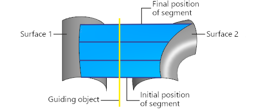
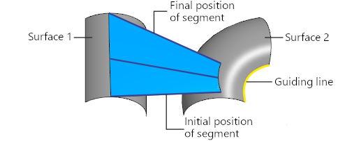
Different types of section segment movement provide different results:
a) parallel to itself, b) along the line
Types of objects used to define the section plane orientation, and the order of their selection are described in the section Objects Defining Orientation of the Section Plane during Movement of the Segment-Section.
|
The object to define the orientation of the section plane should be selected in such a way that this plane intersects with surfaces 1 and 2. Otherwise it's impossible to create a linear surface. |
3.For the given surfaces and directions, several position options for the resulting surface are possible (see Figure). You can select the preferred way of plotting with the Previous result  and Next result
  .
.
4.To check a surface for self–intersections, please enable the Self-intersection check setting. If any self–intersections are detected, a corresponding message will appear on the screen. More details on surface self-intersection...
5.If necessary, set the name of the created surface and its display properties using the controls located in the Properties section. Management of the color and optical properties of objects...
6.To complete the operation, click Create an object  .
.
The created surface will be displayed in the graphic area; its icon  .
.
|
If plotting produces several linear surfaces instead on one (for example, if you have specified non-coherent faces as one of base surfaces), then the process of changing surfaces set automatically starts after the plotting process. Select the surfaces that you want to keep. Details... Each of the resulting surfaces is a separate object. You can independently change their colors, hide them or move them into layers. But they will be registered as created by one feature, i.e. they will all change in case you edit the plotting feature. |
7.To complete operation of the command, click Finish  .
.
See Also