|
Surface adjustment of polygonal object |
Scroll |
Surface of a polygonal object may contain a large number of irregularities, for example, if it is obtained by 3D scanning of a real object. This object cannot be effectively used when building a solid model. To create surfaces suitable for further work, adjustment is performed.
Surface adjustment represents the approximation of surface patches of a polygonal object by surfaces of predefined types (flat, cylindrical, spherical, etc.). As a result of the surface adjustment process, a new surface is built in the model, inscribed within the specified area of the polygonal object's surface, with maximum approximation to the vertexes of the triangles constituting this area.
Later, using the obtained surfaces,It's available to create planes for building section of a polygonal object local coordinate systems and other solid model objects, perform measurements, etc. Additionally, based on such surfaces, It's available to build an entire solid or a surface that closely resembles the original polygonal object (using commands for this purpose). Surface extension, Surface trimming, Knit surfaces).
The figures show the original surface of the polygonal object and the surface obtained as a result of adjustment.
|
|
|
a) |
b) |
c) |
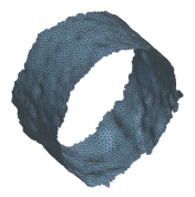
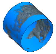
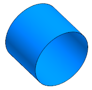
Surface adjustment:
a) original surface of the polygonal object,
b) starting and resulting surfaces, c) resulting surface
To fit the plane size, use the Surface adjustment command  .
.

Step-by-step instructions
1.Specify a surface area of the polygonal object or specify the entire object.
•To specify an entire object, click on it with the mouse in the graphic area. All triangles forming the surface of the polygonal object will be specified.
If the surface of a polygonal object is split into segments (such surfaces can result from importing from JT format files), clicking the mouse specifies not the entire surface, but the specified segment (i.e., all triangles included in this segment).
•To assign a surface area, click Select triangles button  to the right of the Object field. The subprocess of specifying triangles will start. Specify all triangles comprising the required area, and click Create object button. The system will go back to adjusting the surface.
|
Within one command of Surface adjustment,it's available create only one surface of a specific type. Therefore, it is recommended to specify the triangles so that the resulting segment is close in shape to the surface that will be used for approximation. Specifying an entire polygonal object (or its segment) makes sense if it is close in shape to the approximating surface. |

After setting the surface segment in the Object field of the Parameter panel, the number of triangles that make up this segment will be displayed.
2.Select type of a surface, which should be inscribed in the specified area. To do this, in the Surface type list, activate the desired row. The phantom of the surface being created will appear on the screen.
The surface parameters are automatically determined by the system in such a way as to minimize the deviation of the resulting surface from the original data. The approximation accuracy for the given segment can be viewed in the group of reference fields Result (the smaller the deviation values, the higher the accuracy).
3.If necessary, set a guiding object. This will enable to align the created surface relative to the objects existing in the model.
When building a surface adjustment, the guiding object sets the direction of the normal; when building a cylinder, cone, sphere, or torus – the direction of the axis. It's impossible to define a guide object for a spline surface.
The following can be specified as a guiding object:
•straight-line object — for surface alignment, the object itself is used,
•flat object — for surface alignment, the normal to the object is used,
•an object with a rotational axis (cylindrical face, conical face, etc.) — for aligning the surface the object's axis is used,
•build vector — for surface alignment, the object itself is used.
|
If a straight object or an object with a rotation axis is selected as the guide during the building of a cylinder, cone, sphere, or torus, a Make coaxial switch is present on the Parameter panel. To align the axis of the created surface with the guiding object (guiding object's axis), assign the on-off switch to position I (enabled). Otherwise, the axes will be parallel. |

4.For certain types of surfaces, it is possible to view and modify parameters, such as for a conical surface – the slope, for a cylindrical surface – the cylinder radius, etc. The Parameter panel contains fields where the values of these parameters, automatically determined by the system, are displayed.
To change the parameter value, set the toggle switch Manage parameters to position I (enabled) and enter the required value in the field.
5.If the specified surface area is not closed and in the list Surface type, Cylinder, Cone, or Thor is selected, then the option Close is present on the Parameters panel. Enable this option in order to build a closed surface of the selected type based on the results of the approximation of the specified section. This might be necessary when it is impossible to specify all needed surface triangles (for example, if other model objects interfere with the specifying or the surface is inside a hole), as well as if the polygonal object does not contain a closed surface of the required type, but only a section of it.
6.Determine if it is necessary to exclude outliers from approximation (vertexes of triangles whose values fall outside the specified range, see the following point). To do this, the on-off switch Exclude outliers is used.
By default, the on-off switch is in the I (on) position. Initially, all values that fall outside the established range are discarded, and then adjustment is carried out. This requires additional resources but allows for improving the result of surface adjustment with a greater number of irregularities (for example, those obtained by scanning). Additionally, the exclusion of outliers allows for the correction of errors in the specifying of triangles, for example, when triangles that belong to transitional areas of surfaces fall within the specified region.
If the original polygonal object has a sufficiently smooth surface and the fitting area is specified accurately, it's available to disable outlier exclusion by setting the switch to the 0 (disabled) position.
7.Specify a range of values to be taken into account during adjustment. For this, in the field Multiplier (N*σ) enter the number N, which will be used to multiply the standard deviation σ (sigma). The obtained value, counted in both directions from the resulting surface, defines the boundaries of the range.
Vertexes of triangles falling within the given range will be considered during the approximation. The remaining vertexes are considered outliers.
|
The default value for the field Multiplier (N*σ) is 2. If the starting data is not very accurate, and the adjustments results show large deviations (the deviation values are displayed in mm in the Result field group), then the value of N should be decreased. |
|
If Spline surface is selected for approximation, then the elements for excluding outliers and setting the value range are absent. |
8.Evaluate the approximation accuracy using reference fields Result. If the deviations are too large, change the fitting parameters (for example, reduce the range of considered values by changing the number N).
9.Select a coordinate system relative to which the created surface will be located. To do this, use the list SC in the Coordinate system section.
If necessary, it;s available to create a local coordinate system without interrupting the operation. For this, the Design LCS  button is used, located next to the coordinate system selection list. After pressing the button, the subprocess to creation of LCS is invoked. Specify LCS parameters and click Create object button. The system will go back to creating the surface adjustment. The new LCS will be added to the list of coordinate systems and will be automatically specified.
10.If necessary, set the name of the created surface and its display properties using the controls located in the Properties section of the Parameter panel. Management of color and optical properties of objects...
11.To complete the operation, click Create an object  .
.
The model will generate a surface without history, inscribed in the selected section of the polygonal object's surface. The created surface and the original polygonal object are displayed in the graphic area. The Design tree contains a name of the surface and its icon  .
.
12.To complete operation of the command, click Finish  button.
See Also