|
Linear grid of centers |
Scroll |
The linear grid of the centers allows to create axial lines for a group of objects whose centers are located in the nodes of the parallelogram grid. Objects are circles and circular arcs.
A designation includes the centerlines running through the centers of indicated objects.
To create a linear grid of centers, use the Linear Grid of Centers  command.

After invoking the command, the cursor will take the shape of a square "trap".
|
The size of the cursor’s trap can be changed in the dialog for setting up the cursor. |

Step-by-step instructions
1.Set the parameters of a linear grid:
•the slope angle of the first axis relative to the axis of abscissas of the current coordinate system in the Slope of major axis field,
•the angle between the grid axes in the Aperture Angle field.
To set the values of angle, you can use commands of the geometrical calculator.
2.Indicate objects for creation of a grid (a circle, an arc of circles). Names of the selected objects will appear in the Objects field on the Parameter Panel.
Objects for creation of a grid can be selected automatically. To do this, click Auto  to the right of the Objects field and specify objects in the opposite corners of the grid. Details...
In the graphic region, a phantom of the created grid of the centers is displayed.
|
Objects for creation of a grid can be selected before invoking a command. In this case, after its invocation a phantom of the linear grid of centers will appear in the graphic region. |

3.Indicate the option of building a grid using the With breaks option:
•with the option enabled, the centerlines are interrupted if at the point of their intersection there is no datum object (see Fig. a),
•With the option disabled, continuous centerlines are built (see Fig. b).
If each node of the grid coincides with the center of datum object, then the state of the option does not affect the view of the grid.
The length of each axis of the grid is determined by the number of datum objects whose centers lie along this axis. In the process of building, you can extend/shorten the axes by moving the defining points at the ends. For this purpose bring the mouse pointer to the defining point of the grid. The cursor will take the shape of a quadrilateral arrow. Click the left mouse button, and without releasing it, move the defining point. Then release the mouse button.
4.Configure rendering of centerlines using elements in the Parameters section. Details...
5.To complete creation of a linear grid of centers, click Create object  .
.
6.To complete operation of the command, click Finish  .
.
|
|
a) |
b) |
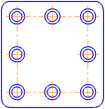
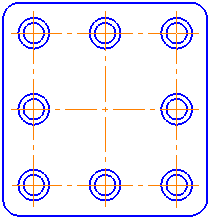
Examples of building a linear grid of centers: a) with breaks, b) without breaks
Notes on the creation of center grids in parametric mode...
See Also
Center mark and center grid mark: Overview
Automatic selection of objects
Objects for creation of a linear grid can be determined automatically. To do this, use Auto button to the right of the Objects field.
To select objects, click Auto, then indicate two objects in the opposite corners of a grid. After indication of the first object, in the graphic region there appears a phantom of parallelogram whose vertex is the center of the indicated object, and the sides are parallel to the grid axes. The second parallelogram vertex follows the cursor (see figure). After the indication of the second object the phantom will cease to be displayed in graphic area.
|
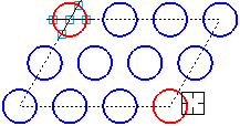
Building a parallelogram for automatic selection of objects
After creation of a parallelogram in the graphic region, all the circles which centers are located inside or at the parallelogram border will be selected, and their names will appear in the Objects field (arcs of circles are not determined on auto-selection). If within a parallelogram the center of concentric circles is located, then as the datum object a circle of the greatest diameter is selected.
To set a parallelogram by several objects, at first indicate the required objects, then click Auto. A parallelogram whose sides are parallel to the axes of grid and run through the centers of the indicated objects will be created. In this case, the phantom will not be displayed in the graphic region.
|
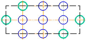
Example of building a parallelogram by four objects (the parallelogram is shown conventionally).
The objects selected manually are highlighted with color.
After generation of a parallelogram, it is impossible to delete automatically selected objects from the list or to add new objects to the list. To change the contents of a group of objects, release the Auto button. Names of automatically selected circles will be deleted from the Objects field. Indicate the required objects manually.
With auto-selection of objects, pay attention to the following. The built parallelogram does not change on change of the slope angle of the first axis of grid and/or angle between the axes, so the set of objects remains the same.
To rebuild a parallelogram, release the Auto button, then press it again. A new parallelogram will be built, and objects will be selected again.