|
Plotting a linear surface by curve and surface |
Scroll |
To plot a linear surface by a curve and a surface, use the Linear surface by curve and surface  command.

Step-by-step instructions
1.Specify the curve along which the segment-section will move. The starting point of a segment will be located on this curve in any position.
The following can be specified as a curve:
•a spatial curve or, in the case of a contour or a broken line, individual segments,
•sketch line or entire sketch (indicating the entire sketch is possible if it contains one object or one chain of objects),
•edge,
•a chain of the above objects in any combination (objects are specified in their junction order).
Face edges, sketch lines, and polyline segments are specified in the model graphic area. To select the entire sketch or broken line, specify this object in the Design Tree or select all the sketch lines or all the segments of the broken line in the graphic area. A spatial curve can be specified both in the Design Tree and in the graphic area. Specifying curves with subordinated objects-curves has Features.
|
If a multi-segment curve or a chain of objects linked in a sequence is used, a surface can be created only when tangents in segment junctions cross with angled lower than 60°. |

The name of the selected object (or objects, if you have specified a chain) is displayed in the field Curve of the Parameters Panel.
The Reverse Direction  button next to this field allows changing the direction of the segment-section movement to the reversed.
2.Specify the surface that will determine the position of the cut-section. For this purpose, activate the Surface field and specify a face of a solid/surface or coherent set of faces of a solid or a surface.
To choose a whole solid or surface, specify it in the Design Tree or select all elements of the solid/surface using the Marquees in the graphic area. A linear surface will be plotted through all the faces of the selected solid or surface, which are located within plotting conditions. Later the plotting result will be changing according to changes in faces number.
If necessary, you can specify several non-coherent faces or faces sharing common edges but belonging to different solids/surfaces. In this case, the surface is constructed on the face positioned closest to the reference curve.
|
It is permissible to have faces, not complying to the plotting conditions, in the list of selected faces. They are simply ignored in the plotting process. If later the shape and/or the position of the faces change such that the building condition is met, the resulting ruled surface will also change. |
Names of the selected objects are displayed in the field Surface.
The Change Direction button next to this field allows you to perform the construction of a ruled surface in a mirror-reflected view relative to the surface that determines the position of the segment-section.
When you finish selecting a curve and a surface, a phantom of a linear surface being created with default settings is displayed in the graphic area.
3.Specify the direction of the slope angle measurement of the section segment. To do this, use the group of buttons Direction. By default the angle is measured from a projection on the section plane from a normal to a selected surface, passing through a point on a curve (see Figure). If the button in the group is pressed Perpendicularly  . You can press Touch
  button. In this case, the tangent direction is determined by plotting a 90° angle from the normal projection. Then the angle for the section segment is measured from this direction.
4.Specify the slope angle for the segment-section using the elements of the Deviation group. Select a type of the function that will be used to determine the angle and set the values for the selected function. More details on setting the angle of the segment...
5.Set the length of the segment-section by defining the displacement of its end point relative to the starting point using the elements of the Move group. Select a type of the function that will be used to determine the offset and set the values for the selected function. More details on setting the length of the segment...
6.Specify an object defining the orientation of the section plane during the movement of the segment. To do this, use controls of the Design section. The type of movement can be selected using the Section Movement. The following options are available:
 Parallel to itself — the segment in each of its positions is in the plane perpendicular to the straight-line direction set by the guiding object (figure a).
 Along the line — the segment in each of its positions is in the plane perpendicular to the specified guiding line — a curve of arbitrary shape (Figure b).
|
|
a) |
b) |
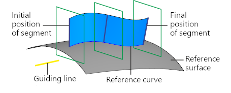
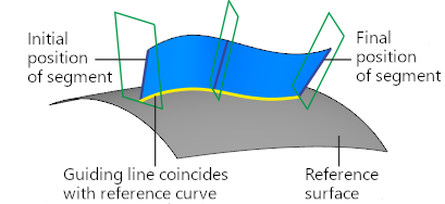
Different types of section segment movement provide different results:
a) parallel to itself; b) by line
Types of objects used to define the section plane orientation, and the order of their selection are described in the section Objects Defining Orientation of the Section Plane during Movement of the Segment-Section.
|
The object to define the section plane orientation should be selected in such a way that this plane intersects with the curve and surface objects specified for plotting. Otherwise it's impossible to create a linear surface. |
7.To check a surface for self–intersections, please enable the Self-intersection check setting. If any self–intersections are detected, a corresponding message will appear on the screen. More details on surface self-intersection...
8.If necessary, set the name of the created surface and its display properties using the controls located in the Properties section. Control of the color and optical properties of objects...
9.To complete the operation, click Create an object  .
.
The created surface will be displayed in the graphic area; its icon  .
.
10.To complete operation of the command, click Finish  .
.
Tips
•You may use the curve selection (in item 1) marquee. If marquee catches several objects or object chains available for selection, the first of them is selected as a curve. In this context, 'first' refers to the object constructed in the model earlier than the others.
If the marquee catches some solids, surfaces, or their faces, those will be selected as a base surface (see item 2).
•You can set linear and angular parameters using the geometrical calculator.
See Also