|
Connecting and Editing the BOM Item Geometry |
Scroll |
Inclusion of a positional leader line in the BOM item is a prerequisite for:
•transfer of numbers assigned to items after the calculation of reference numbers from the BOM to the document connected to it;
•transfer of designations of zones in which reference numbers are located from the drawing to the attached BOM.
Inclusion of the relevant drawing or model items into the BOM item allows you to quickly find an image of this BOM item (for example, part or assembly unit) in the assembly drawing or in the assembly model.
Therefore, we recommend to include the positional leader line and, if possible, the item image or model in the BOM item.
|
The leader line may be the only graphic object within the geometry of the BOM item. |

If the document contains items with properties, then the geometry of the corresponding BOM items is formed automatically.
You can control the item geometry in the subordinate mode of operation with BOM items. Changing the geometry of an item in a BOM document is not possible.
Viewing the geometry of items is possible when working both in the subordinate mode and in the BOM document.
You can include the geometry only in the base BOM items.
Immediately after the inclusion of the positional leader line in the BOM item, the reference number on the leader line landing is replaced with a link to the Ref. No. property of the product constituent part. The default link color is dark blue; you can change it in the dialog for setting up the color of text elements.
The positional leader line can be included in several BOM items. In this case, landings are automatically added to it to accommodate reference numbers retrieved from the items. Numbers are placed on the landings in the ascending order. Duplicate items grouped together have a single reference number, therefore, when connecting a leader line to such items, additional landings are not formed.
The reverse situation, i. e. the inclusion of several positional leader lines in the geometry of a single BOM item, is also possible. In this case, the reference number of the BOM item will be transferred to the landings of all attached leader lines (i. e., they will have the same reference numbers).
|
If the leader line is included in the geometry of the BOM item, then adding landings with arbitrary reference numbers will not be possible. You can create only landings with text or enter text on existing landings. |
Automatic generation of BOM item geometry
If the BOM item is generated automatically based on the properties of the document item, then this document item will always be included in the geometry of the corresponding BOM item.
For example, an assembly component or a macro-element inserted in a drawing is automatically included in the BOM item created on the basis of the properties of this component or macro-element. You can check it by viewing the geometry of objects.
You cannot exclude a document item from the geometry of its corresponding BOM item. If required, you can append the geometry of this BOM item with any other items.
When working with an assembly model, not only components and solids but also positional leader lines are automatically included in the BOM items if they are attached to these components and solids.
When creating associative views of a model in a drawing, model BOM items are transferred to it. The lines forming the projections of the components and solids are automatically included in the geometry of the corresponding BOM items. If the transfer of detailing elements to views is enabled, then the positional leader lines available in the model are displayed in the drawing. These leader lines are also automatically included in the geometry of the corresponding BOM items.
If the reference numbers are added to the drawing manually, and also if the drawing is not associative, then you cannot unambiguously determine to which constituent part of the product the leader line belongs. In these cases, positional leader lines should be included in BOM items manually.
Managing the Geometry of BOM Items
Step-by-step instructions
1.Open the document (drawing or assembly) and run the subordinate mode of working with BOM items in it.
After activating the subordinate mode, a separate tab is created in the KOMPAS–3D window. For convenience, we recommend moving it to a new window (but you can also work with different tabs in the same window). To do this:
•run the Move to New KOMPAS Window command from the context menu on the tab header
•or drag the header with the mouse outside the tabs row.
Place the KOMPAS–3D windows so that they do not overlap.
2.On the document tab, select the items that should be part of the BOM item. Don’t forget the positional leader line!
If you want to remove the geometry from the BOM item, no item should be selected.
3.On the subordinate mode tab, select the BOM item to change the geometry.
4.Run the Change Set of Attached Geometry command  .
.

5.Click the appropriate button in the dialog that appears on the screen (see figure):
•Add — this button is available in the dialog if items were selected in the document;
•Replace — this button is available in the dialog if items were selected in the document and the BOM item being edited already has geometry;
•Clear — this button is available in the dialog if no items were selected in the document.
|
|
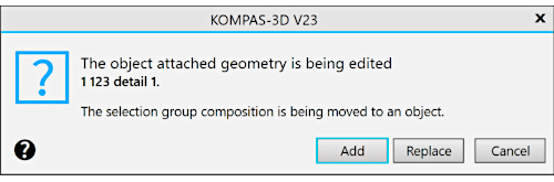
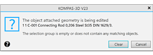
BOM item geometry editing dialog
a) add/replace geometry; b) remove geometry
|
Be careful when changing the geometry of the BOM item, since this operation cannot be canceled. For restoring the previous state of the item geometry it should be edited again. |
|
When working in a drawing, the geometry can be added to the BOM item simultaneously with the item creation. To do this, before running the Add BOM object command, select the required graphic objects (including the positional leader line). |

If the BOM items have geometry, then you can simultaneously open the document and the BOM to which it is attached to view the geometries attached to particular items. In other words, you can quickly find the images in the drawing or model of the assembly, the records of which are included in the BOM (see figure below).
Step-by-step instructions
1.Open the BOM and the attached document.
|
To load a document attached to the BOM, it is convenient to use the Edit in Window button in the Assembly Management command. After the document opens, close this command. |
Documents will open on different tabs in the same KOMPAS–3D window. For convenience we recommend moving one of them to a new window. To do this:
•run the Move to New KOMPAS Window command from the context menu on the tab header of the document
•or drag the header with the mouse outside the tabs row.
Place the KOMPAS–3D windows so that they do not overlap.
If both the assembly and the assembly drawing are attached to the BOM, then you can open both of these documents and view their geometry simultaneously.
2.To facilitate working in the graphic area of a drawing or assembly, run the Show All command (or press <F9>).
3.Activate the BOM and select any BOM item in it.
4.Run the Indicate Attached Geometry command  .
.
The system will switch to the mode of displaying the geometry of the BOM items. In the graphic area of the drawing or assembly, graphic items or three–dimensional components that are part of the selected BOM item will be selected.
5.To view the geometry of other items of the current BOM, select these items using any method (with the mouse or keyboard).
The mode of displaying the geometry of a BOM item will be active as long as the Highlight Attached Geometry command is active.
6.To exit the geometry display mode, run the Highlight Attached Geometry command again.
|
You can also view the geometry of BOM items when working in the subordinate mode: it also includes the Highlight Attached Geometry command. |
|
To enlarge the graphic area, enable the Hidden toolbars modeby clicking the Toolbars Display button in the right part of the KOMPAS-3D window header. The toolbar panel and control panels will no longer appear on the screen. Use the Main menu for running commands. To restore the display of toolbars, depress the Toolbars Display button. |

Viewing the drawing geometry included in the BOM item:
an item is selected in the BOM, the geometry of this item is highlighted in the drawing and assembly