|
Dialog Output parameters in DXF and DWG formats |
Scroll |
The dialog appears on the screen when exporting to the format The DXF format or DWG.
It allows you to configure export options.
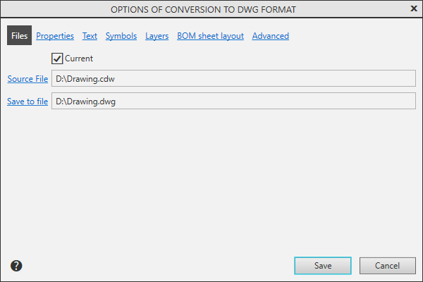
Files page
Present in the dialog when manual invoking commands for export.

Description of Controls
The element |
Description |
|
Current |
To select the current document to be exported, enable this option. |
|
Source File |
To select an exported file (or document groups) click this link. The file name is displayed in the field to the right. |
|
Save to file |
To select the resulting file, click this link. The file name is displayed in the field to the right. |
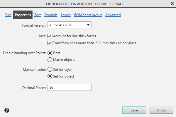
Properties Page
Description of Controls
The element |
Description |
|
Format version |
Select the format version DXF/DWG from the list to save export results. For details about selecting a format version... |
|
Lines |
A group of options that controls writing to the resultant line thickness information file used in the document. Enabling the option Account for line thickness allows you to transfer the thickness of the lines set for printing to the resulting document. When you turn on the option Lines with a thickness of more than 2.11 mm to convert into polylines, objects having a line thickness of more than 2.11 mm will be recorded as polylines. This option is available when the option Account for line thickness is enabled. More about Setting line thickness.... |
|
A group of options that allows you to customize the recording points. If you want to convert the points into similar AutoCAD objects, please enable the Dots setting. Please enable the Macro Objects option if you want to preserve the original style (Asterisk, Envelope, etc.) and color of the points. More details on point transmission... |
||
Maintain color |
A group of options that allows you to customize the recording of colors of objects. Enable the option Set for layer so that the objects have the colors specified for the layers containing these objects. If the objects should maintain the colors as configured for these objects, please enable the Set for object setting. More details on setting object colors... |
|
Decimal Places |
Specify the accuracy with which the coordinates of the objects should be recorded in a symbol file *.dxf. More information about setting precision for saving coordinates... |
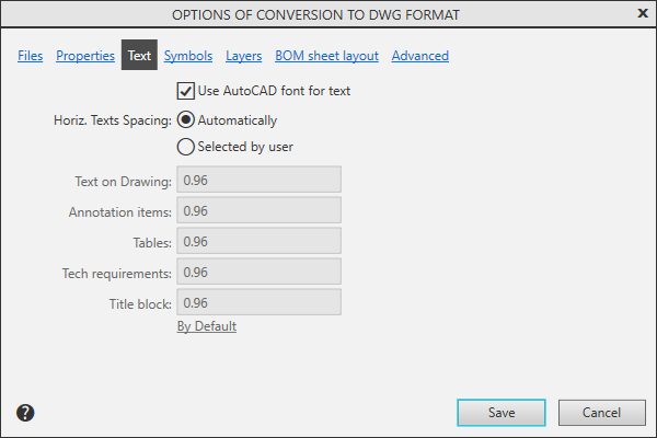
Text Page
Description of Controls
The element |
Description |
|
Use AutoCAD font for text |
Enabling this option when exporting to a format DXF/DWG convert fonts KOMPAS-documents in fonts of AutoCAD format. More information about text entries... |
|
Horiz. Texts Spacing |
A group of elements that manages the dimensions of text objects. Enabling the Automatically option allows you to adjust the dimensions of the resulting text objects resulting from the export to the dimensions of the original ones. To set the required horizontal factors for exported text objects, enable the Selected by user option and enter the desired horizontal values for different types of labels. To return the default narrowing coefficients, click the link By Default. More details on setting up horizontal text spacing... |
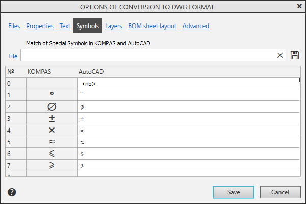
Page Symbols
Using this page, you can customize the matching characters. Details...
Description of Controls
The element |
Description |
|
Character Map |
Allows you to edit the correspondence between special characters KOMPAS and sequences of characters. The table is available if the option Use AutoCAD font for text On the page Text included |
|
|
Save to file |
Click this button to save the settings in the KOMPAS-3D and AutoCAD special character mapping file (*.acs). |
File |
To connect a previously saved symbol mapping file (system file KOMPAS with the extension ACS), click this link. The file name appears in the box to the right. |
|
|
By Default |
To return to the default matches, click this button. |


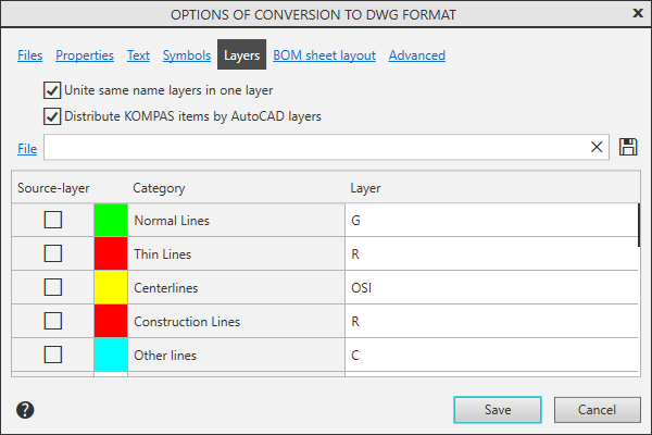
Page Layers
It allows you to customize writing of objects located on different layers. Details...
Description of Controls
The element |
Description |
|
Unite same name layers in one layer |
Enabling this option means that after defining states (see tableThe layers will be divided into groups with matching parameters (states, names, colors). The layers of each group will be united into new — resultant layers. For more details on merging layers.... |
|
Distribute KOMPAS objects by AutoCAD layers |
Enable this option to adjust the distribution of objects by layers. The window displays a list of categories of objects of the KOMPAS system and the names of layers in AutoCAD, on which these objects will be placed by default, as well as the colors of the layers. More information about objects placement in layers... |
|
|
The object type category (Points, NURBS curves, Hatches etc.) has priority over the line style category (Main lines, Fine lines etc.). Hence, if an object belongs to two categories at the same time (e. g. a NURBS curve with Main line style), this object will be placed in the layer defined for the type category. |
|
|
Save to file |
To save the settings made in the file, click this button. In the dialog that appears, specify the name of the file to be written. The software will generate a binary file with information about AutoCAD layer names and colors for KOMPAS-3D objects (*.LAC). |
File |
Click on this link to connect the file created earlier with the *.LAC extension. The file name appears in the box to the right. |
|
|
By Default |
To load the default setting, click this button. |

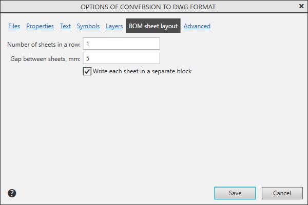
BOM sheet detailing page
The page allows you to set the placement parameters of multi-page BOMs in the format DWG/DXF. More about exporting BOMs...
Description of Controls
The element |
Description |
|
Number of sheets in a row |
Enter or set by the counter the number of sheets of the BOM that should be placed in the horizontal row. The number of rows is automatically determined based on the placement of all the BOM sheets. |
|
Gap between sheets |
Enter or set the distance by the counter (in millimeters), which must be left between the outer frames of the BOM sheets. |
|
Record each sheet Specifications as a separate block |
Enable this option so that segments and texts representing a single BOM sheet are combined into a block. This setting is also valid for single sheet BOMs. |
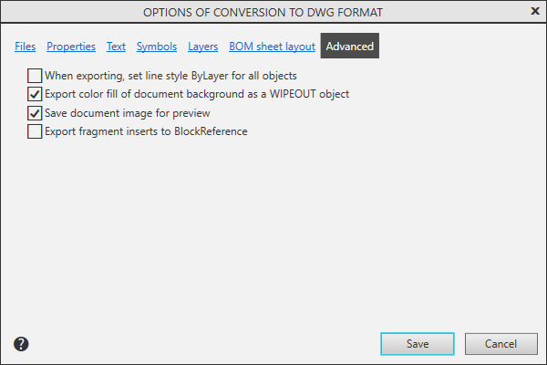
Advanced page
Using this page, you can specify advanced export options. Details...
Description of Controls
The element |
Description |
|
When exporting, set line style ByLayer for all objects |
Enabling this option allows you to assign the line type By layer. to all objects. If this option is disabled, the new line types depend on the styles of these lines in the source document. |
|
Export color fill of document background as a WIPEOUT object |
When this option is enabled, the fill is exported as a Wipeout object. If the setting is disabled, the fill is exported as gray fill. |
|
Save document image for preview |
Enabling this option allows you to display thumbnails of document images in Windows Explorer. |
|
Export fragment insertions to BlockReference |
Enable the option that all block occurrences corresponding to inserts of the same fragment have a common definition. If this setting is disabled, each instance of the block will have its own definition. |
After setting the parameters, click the Save button. The setting is written to the file. dxflib.cfg or dwglib.cfg will be used to record subsequent files. If you need to change the recording parameters, call the export settings dialog and make the necessary changes.
Click Cancelto discard all changes to the settings and exit the dialog.
More details on importing and exporting in DXF/DWG format...