|
Diagnostics of a parametrized sketch |
Scroll |
In this section:
Color indication of objects in the sketch
Sketch with erroneous projection links
Depending on whether the sketch objects have degrees of freedom, the sketch can have a status of Defined or Undefined. These statuses are shown by the symbols "+" and "-" respectively.
• Completely defined sketch — a sketch whose objects do not have a single degree of freedom in the sketch coordinate system.
• Undefined sketch — a sketch containing at least one object that has degrees of freedom.
To delete degrees of freedom on sketch objects, apply constraints.
|
•It is recommended that sketches in the model are defined. In this case, the process of solving the systems of equations for sketches will be more stable. •In the process of creating constraints and dimensions in the sketch, may appear ambiguous constraints (these include excessive and poorly conditioned constraints). Icons for such restrictions are orange in color. The presence of ambiguous constraints does not change the status of the sketch — the sketch remains defined or underdefined (depending on the presence of degrees of freedom). Ambiguous constraints do not hamper operations with the model and can remain in the sketches, i.e., the orange color is not considered an error. It talks about how the system of constraints is suboptimal and points out areas where it can be improved. You can modify the sketch constraints set or leave it as is. •When applying constraints to sketch objects, some controlling dimensions may be locked (locking dimension means that its value cannot be changed). In the sketch, locked dimensions, as well as ambiguous constraints, are displayed in orange color. Their presence does not affect the status of the sketch. If you need to control the image using a locked dimension in further work, change the sketch constraint system so that the lock disappears. In other cases, you can leave everything as is. |

In some cases, the system of created constraints may operate incorrectly. Then the sketch is assigned the status Sketch requiring attention. This status corresponds to the symbol "!".
• Sketch requiring attention contains an unreliable constraint system which can lead to errors in the model or cause problems during editing.
|
For correct operation, it is recommended to modify the set of constraints/dimensions of the sketch requiring attention |

Symbols indicating the sketch status ("+", "-", "!") are displayed on the sketch mode icon  and in the Design Tree before the sketch name. For example, when editing an undefined sketch, the sketch mode icon appears as
  , while for a defined sketch it appears as
  .
.
The sketch status changes automatically when restrictions are added/removed. More about changing the status of the sketch and its objects...
Color indication of objects in the sketch
Geometric objects in the sketch have different colors depending on whether they have degrees of freedom.
If an object has at least one degree of freedom, then its color matches the current style of rendering. When an object looses all degrees of freedom, its color changes: by default, the object becomes dark green if display theme of interface is Light, and purple if Dark. If the objects, which do not have any degrees of freedom (i.e., fully defined objects), need to have a color, you can configure in dialog it's settings for displaying constraints and degrees of freedom.
Dimensions in a sketch have the following colors:
•Controlling dimensions — black for Light interface theme and white for Dark,
•Info Dimensions — gray,
•blocked dimensions — orange.
The figure shows an example of a predefined sketch with default object indication settings (in KOMPAS-3D, the Light theme is selected and the workspace background is set to white).
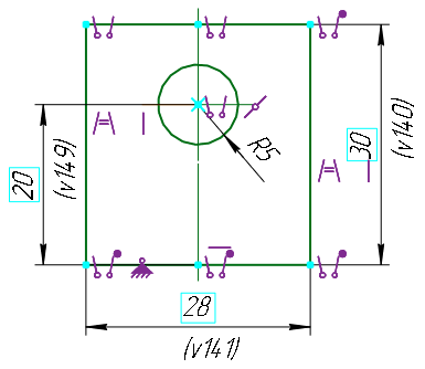
Display of a predefined sketch
Sketch with erroneous projection links
When building a sketch, you may usesnap to model objects, projecting model objects into a sketch, creating the curves of intersection of model objects with the sketch plane.. In this case, projection links are created between the sketch objects and the model objects.
As a result of editing the model, the model object associated with the sketch object may be changed in such a way that projection links cannot exist, for example, if the change in the shape or position of the model object leads to the degeneration of its projection in the sketch. Projection links may be also lost if the sketch plane position is changed.
If erroneous projection links appear in a sketch, an error occurs: "A link was lost" or "Degenerated edge/face/plane projection". Such a sketch is marked in the Design Tree as erroneous.
In the sketch editing mode, one can see which objects contain errors. Icons for erroneous constraints in the graphic area are colored red. A symbol "x" appears next to them. The dimensions labeled to the lost objects and the lost objects themselves also have a red color.
|
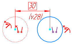
Display erroneous projection links
If an erroneous constraint is included in a group of several constraints of the same type, then the icon representing the group also turns red and is marked with the symbol “x” (for constraint groups, see section Viewing objects affected by constraint). The figures show the erroneous constraint Parallelism, which belongs to the group of constraints of the same type.
|
|
a) |
b) |
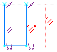
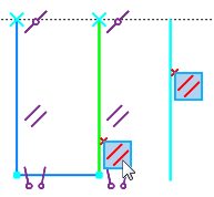
Display of an erroneous constraint, included in the group of constraints with the same type
a) the group of constraints is collapsed,
b) the group of constraints is expanded, an erroneous constraint is activated.
To fix the error in the sketch, delete invalid projection links.
See Also