|
Element section by path |
Scroll |
In this section:
Objects used as a section. Order of specifying objects
Features of specifying objects of different types
Building a solid and thin-walled element depending on the section object
Using a solid as a tool for cutting by path
Objects used as a section. Procedure for specifying objects
As a section Element by path The following objects can be used:
•a sketch or a closed sketch area (see section Using sketches in operations),
•a planar curve, closed or open (the curve can consist of several segments),
•edge of a flat face,
•a flat face.
Specify the desired object in the graphic area or in the Design Tree of the model. The name of the selected object will appear in the Section field (if an area is selected in the sketch to the text, the word Area is added to the field).
The features of selecting objects of different types are given below.
|
The object can be selected before starting the operation. If it is suitable for defining the section, it automatically becomes the section of the element along the trajectory. If the object cannot be used as a section but can define the path of its movement, then it is selected as the path. More details on the trajectory assignment... If the object cannot be either a section or a trajectory, the selection is reset. An area in a sketch is specified only during the execution of the command. |

In addition to the above-mentioned objects, you can use a solid for moving along the path. That is possible if The operation result is a is a cut or intersection. More details on using a solid as a tool for cutting by path...
Features of specifying objects of different types
•Sketch — specify one of the sketch's objects in the graphic area of the model or specify the sketch itself in the Design Tree.
By clicking the  icon in the Section field, you can also edit the selected sketch if required.
If the required sketch does not exist in the model, you can build it without interrupting the command. To do this, click the Create Sketch button  on the right side of the Section field. Will start sketch placement process, and then the system will switch to the Sketch mode for Creating geometry. Perform the steps necessary to build and complete the sketch mode.
•To select an area in the sketch, click inside the required area.
•Flat curve — specify a flat curve (for example, a circle, an arc of a circle, a spline on a flat face) in the graphic area of the model or in the Design Tree. To select a curve consisting of several segments (for example, a flat broken line or a flat contour), specify one of the segments in the graphic area or specify the curve itself in the Design Tree.
|
A spatial segment cannot be a section of a path element. If it is required that the section has the form of a line segment, use a line segment in the sketch, a contour on the flat face in the form of a line segment, etc. |

|
Using curves with subordinate curve objects (projection curve, intersection curve, etc.) has its own features. Details... |
•Edge of a flat face, flat face — specify the required object in the graphic area.
|
The edge can be selected as a section if at least one of the faces intersecting at the edge is flat. This face defines the plane of the sectioning object. If both faces are flat, the outcome of the construction depends on which of the faces determines the flatness of the object. The selection of the face is performed by the system. Specify another face to set the plane is not possible. To obtain the required result, use the contour or sketch with the edge projection built on the desired face. |
Building a solid and thin-walled element depending on the section object
Depending on the object selected as a section, the resulting construction can yield a solid or thin-walled element (see table).
|
The table shows the options for the element whose cross-section retains its shape along the entire trajectory. If an element is created with Changing section shape (Such construction is available for a sketch-section), then creating a thin-walled element is impossible. |
Building a solid and thin-walled element depending on the section object
Object |
Result of plotting |
|
A flat face; a closed flat curve (edge); a sketch containing one closed contour; a sketch area |
It is possible to build both solid and thin-walled elements. |
|
An open edge; an open flat curve, a sketch containing one open contour |
A thin-walled element is being constructed. |
|
Sketch containing several contours |
•If all contours are open, then a thin-walled element is built. •If all contours are closed, then a solid element is built, in this case: •intersecting contours give an element whose cross section is an association of areas bounded by contours, •non-intersecting contours create an element with holes (if the contours are nested within each other with a nesting level of 1) or an element from separate parts (if the contours are not nested within each other, or are nested with a nesting level greater than 1). •If there are both closed and open contours in the sketch, then a thin-walled element is built. |
Using a solid as a tool for cutting by path
When selecting the Operation Result Subtraction  or Intersection
  can be used to create an element along the trajectory of a solid present in the model. While the operation is executed, this solid will be moved along the selected path and intersect solids located in the operation application area. An example of cutting with a solid by path is shown in the figure.
|
|
a) |
b) |
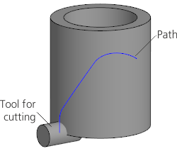
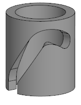
Cutting with a solid by path
a) source objects; b) cutting result
You can only use solids built in the current model to cut by path.
To select the required solid, specify it in the Design Tree. You can also select the solid in the graphic area using a marquee or by enabling the corresponding Filter When the filter is enabled, to select the body, it is sufficient to specify any of its elements.
The name of the selected object is displayed in the Section or solid field.
Using a solid to cut by path has the following features:
•only a solid element can be built,
•The type of movement along the path Orthogonal to Path is not available (see section on selecting type) Type of section move).
|
A solid selected as the cutting tool by path becomes hidden in the graphic area after the element is built. You can perform various actions with the solid by specifying it in the Design Tree but you cannot enable its display in the graphic area. If the element by path is deleted, the solid will become visible again. |