|
Parameters of changing cross-section shape |
Scroll |
If the cross-section of Element by path is a sketch containing a closed contour (for specifying the section, see section Element section by path), you can build an element whose section shape is changing along the path.
Setup of the section modification parameters is performed in the Changing cross-section shape section of the Parameter panel. To perform the setting, set the Changing shape on-off switch to position I (enabled).
The shape of the section at each point of the trajectory is determined by the values of the variables corresponding to the dimensions of the sketch. These values can be calculated in the following ways:
•In accordance with the function defined by a linear law, a cubic law, or a curve by law,
•in accordance with the function specified by the values at certain points of the trajectory.
|
If the required dimension with a variable is absent in the sketch, you can add it without interrupting the current operation. To do this, start editing the sketch by clicking the |

 icon in the
 Moreover, the shape of the section when moving by path may change under the influence of parametric constraints, which linked the sketch elements to the objects of the model — guiding objects. Parametric constraints are accounted regardless of the method used for calculation of the values of variables.
Examples of various methods for changing the section shape when building an element by path are presented in the figures.
|
|
a) |
b) |
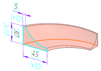
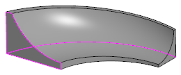
Section parameters are changed according to a linear law:
a) phantom element, b) building result
|
|
a) |
b) |
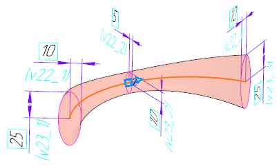
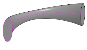
Parameters of section change as per the function defined by values at points:
a) phantom element, b) building result
The figures below show the building of an element whose section is tanged by one of its vertexes to a plane built in the model (the connection is made through constraints Merge points and Point on curve).
|
|
c) |
d) |
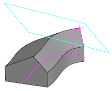
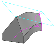
Influence of guiding plane on the building result:
a) Changing the shape of the section is disabled, the link with the plane is not taken into account,
b) section shape change enabled, element built considering the guiding plane
Changing section dimensions according to specified laws
Modification of section dimensions based on values at trajectory points
Changing the shape of the section consistent with the given constraints
The resulting surface is built in such a way that there is a smooth transition between adjacent sections.
The obtained surface can be split into faces at the joints of the trajectory segments/segments of guiding objects, if these segments are joined tangentially. Splitting is performed when the Split to edges option is enabled (the option is present on the Parameters bar if the section shape changes along the path).
|
To build an element with a changing section shape, it's necessary to: •ensure that sections along the entire trajectory do not have self-intersections, •in order for trajectory segments to connect tangentially. |

If necessary, you can view the dimensions and shape of a section at various points along the trajectory. More details on checking the section shape...
Changing section dimensions according to the specified laws
To make the dimensions of the section sketch vary according to the specified laws, set the switch By laws/By values at points to the position By law. The table Variables, in which variables of sketch dimensions will be entered, will be displayed on the Parameter panel.
The table Variables contains the following data:
•variable name,
•value of a variable set in the sketch,
•dimension type to which the variable pertains.
By default, the table is empty. It is required to add the variables of sizes to the table and specify the law of change of their values.
Step-by-step instructions
1.Form a set of variables in the Variables table using the buttons located above the table.
•To add variables of all dimensions marked in the sketch to the table, press Read variables  button. The variables will appear in the table. Each of them will correspond to a separate line.
•To add a variable of one of the sketch dimensions to the table, press the Insert variable button  . In the Variables Select the row of the required variable and click Paste. The dialog box will close, and the variable will appear in the table.
2.Set a change law for each variable.
2.1. Select the row of the variable in the table.
2.2. Using the element group Function Type, select the function that will be used to determine the variable value, and set the parameters for this function (for example, for a linear or cubic function, specify the variable values at the starting and final positions of the segment). The function selection elements appear below the Variables table when a variable row is selected.
To learn more about setting the function of changing the parameter...
If changing the value of a variable is not required, it's available to leave it in the table (without selecting a function and entering values) or delete it. In the latter case, you need to specify the line of the variable and press the Delete button  , which appears above the table when the line is specified.
Modification of section dimensions based on values at trajectory points
To specify section dimensions at required points along the trajectory, set the switch By laws/By values at points to By values at points position. On the Parameters panel, a table of trajectory points will be displayed.
The table contains the following data:
•distance to the point from the trajectory's origin in %,
•distance from the start of trajectory to the point, mm,
•name of the trajectory object with which the point is associated (if any).
By default, two points are displayed in the trajectory points table — the starting point and the ending point. It requires adding the necessary points and setting the section dimension values at these points.
Step-by-step instructions
1.Create a set of path points. To do this, add points and set their position.
To add points, use the buttons above the trajectory point table (the buttons appear when a table row is specified).
•To add a point between the current and previous points, click the Insert the value before the current one button  .
.
•To add a point between the current point and the next point, press the Paste value after current  . button.
By default, the newly created point divides the segment between adjacent points in half. There are several ways to modify the position of a point:
•Enter offset from start along curve in % of its length in column %,
•Setting offset from the start of the trajectory along the curve to the specified length in column Length.
•Setting the snap point — in the graphic area, a point object of the trajectory is specified, with which the point will be associated. Such an object can be, for example, a vertex of a trajectory segment or a point object created on a section of the trajectory.
2.Add the sketch dimension variables to the Variables table (this table is displayed on the Parameters panel when any row in the trajectory points table is selected). Adding variables is done using the buttons located above the table.
•To add the variables of all dimensions set in the sketch to the table, click Read variables . The variables will appear in the table. A separate line will correspond to each of them.
•To add a variable of one of the sketch dimensions to the table, click the Insert variable button . In the Variables select the line of the required variable and click the Paste button. The dialog box will close, and the variable will now appear in the table.
|
The set of variables in the table is the same for all trajectory points. If necessary, you can delete rows of variables whose values should not change. |
3.Set the values of the variables at selected trajectory points.
To set variable values for a required point, select its row in the trajectory points table and enter variable values into the cells of the Variables table.
Set the values for the remaining points in the same way.
Changing the shape of the section consistent with the given constraints
When modifying the shape of the section, the existing constraints in its sketch, which link the sketch objects with the model objects, are taken into account. Such model objects in the context of constructing an element over the trail are called guiding objects. These objects can be:
•faces and edges of solids and surfaces,
•3D curves,
•coordinate and construction planes and axes,
•sketches,
•solids, surfaces, consisting of one face.
To ensure that the constraint is considered during the element building, it must be applied to a sketch object and a curve (or point) obtained from the intersection of the guiding object with the sketch plane. That is, when creating the sketch, you need to invoke the command. Objects of intersection  and specify the required guiding object. Depending on the specified object in the sketch, intersection objects of a certain type will be created – points, curves, and straight lines (see section). Intersection of the sketch plane with objects of different types). Next, between the sketch object and the intersection object, the necessary constraint is created (for example, Merge points , Point on curve, Tangency etc.).
|
•If the intended guiding object is a contour or curve composed of multiple segments, then when building the intersection curve, you should specify this contour (curve) in the Design tree. •Guiding objects should be created before the section sketch. If a point of intersection with the path is required to be built in the sketch, it must also be created before sketching. |
If the constraints are created as required, after setting the on-off switch Changing shape to position I (enabled) on the Parameter panel, a Constraints list appears, displaying the constraints that affect the shape of the section. If there are no suitable constraints in the sketch, then this list is unavailable.
|
All the constraints involving intersection objects are taken into account when building an element along the trajectory. It's impossible to select which constraint will be considered and which will not. If the constraint should not affect the building (for example, a constraint linking the sketch to the projection of some static object — vertexes or edges), then this constraint needs to be removed. Instead of it,it's avaliable to use, for example, a constraint with an intersection object, which should be rebuilt in each section (the intersection point with the guiding curve or trajectory, the curve of intersection with the guiding surface). |
To ensure the element is correctly built considering the existing constraints, the following conditions must be met:
•The guiding curves (surfaces) must intersect the plane of the section sketch,
•The guiding curves (surfaces) must be positioned so that the points (curves) of their intersections with the sketch plane are unambiguously defined.
•Trajectory and guiding curves should not have multiple bends.
|
It is recommended that the section sketch has the status Defined (see Section Diagnostics of parametrized sketch). This allows to obtain a predictable result of building. |