|
Angular Dimension |
Scroll |
To place an angular dimension in a three-dimensional model, use the Angular Dimension  command.

Step-by-step instructions
1.Set the angle sides. To that end, in the Design Tree or in the graphic region specify the required objects: two rectilinear, two flat, or one straight-line and one flat. Their names will appear in the fields Object 1 and Object 2 on the Parameters toolbar. In the graphic region, a phantom of dimension will appear.
|
Labeling the angular dimension between two rectilinear objects is possible only if these objects lie in the same plane. |

2.Select dimension type using the Type group of buttons:
 Minimum angle — dimension is set to an acute angle,
 Maximum angle — the dimension is set to an obtuse angle,
 Angle larger than 180 degrees — Dimension is set to an angle greater than 180 degrees.
The type of angular dimension is determined in the same way as on creation of a dimension in the graphic document. Details...
3.Select the option of drawing the leader lines of the dimension by pressing the required button in the Leader linesgroup:
 Not from center,
 From center.
4.Set up dimension text options. To that end, click in the Text field on the Parameter Panel, or press any of the alphanumeric keys on the keyboard. This will start the Add Text subprocess, and the graphic region will display the label entry table and an additional Parameter Panel. Tuning is performed the same as on creation of a dimension in the graphic document. Details...
5.Set the number of decimal places in the dimension text. That is done the same way as during creation of dimension in the graphic document. Details...
6.Set a dimension tolerance. The order of assigning a tolerance is the same as on creation of a dimension in the graphic document. Details...
7.Specify the placement option for the dimension text using the Text Location group of buttons. Setting up the position of a label is performed in the same way as on creation of a dimension in the graphic dimension, with the only difference: on placement of a label on the landing, the landing can’t be rotated using the <Ctrl>key. Details...
8.Set up the Drawing of dimension arrows.
9.Specify the option of arrangement for the dimension text relative to the dimensional line by pressing the required button in the Text Location group:
 Parallel, above line,
 Parallel, in line break,
 Horizontally, in the line break.
10.If necessary, set the name and color of dimension using the elements of the Properties sector. More about managing object colors...
11.Set position of the dimension line and text.
•If automatic, fixed, or manual placement of the dimension text is selected, then the specified position of the dimensional line determines the position of the dimension text. After indication of this position, creation of the dimension completes automatically.
•If placement of a dimension text on the landing is selected, then the specified position of the dimensional line determines the origin of the leader line. In this case, it is necessary to set position of the landing. After indication of the landing position, creation of a dimension completes automatically.
12.To complete operation of the command, click Complete  button.
The base plane of a dimension is determined automatically.
•If a dimension is labeled between two rectilinear objects, then it is placed in the plane that runs through these objects (fig. a).
•If a dimension is placed between rectilinear and flat objects, then it is positioned in the plane running through the selected rectilinear object and its projection onto the selected flat object (fig. b).
•If a dimension is set between two flat objects, then it is placed in the plane perpendicular to the line of intersection of these objects (Fig. c). The projections of a plane for labeling a dimension onto selected flat objects are displayed as hatched lines.
A dimension labeled between two flat objects can be moved along the line of intersection of these objects. For this purpose, while editing the dimension, move the characteristic point with the mouse on its vertex to the required distance.
|
Projection lines are displayed if the dialog for setting up the dimensions and designations display The option Connecting lines is enabled. |
|
|
|
a) |
b) |
c) |
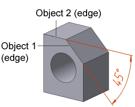
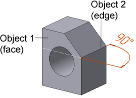
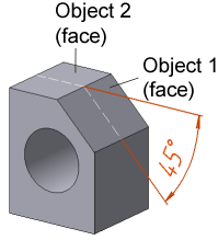
Angular Dimension:
a) between two edges, b) between an edge and a face, c) between two faces
When the angular dimension is edited on the Parameter Panel, there is Change Direction  button. The button allows for directing dimensional lines to other side, saving their length and the selected type of dimension.
See Also
General information. Controlling and informational dimensions in the model