|
Linear Dimension |
Scroll |
To label a linear dimension in a three-dimensional model, the Linear Dimension  command is used.

Step-by-step instructions
1.Select objects for dimensioning.
The object names will appear in the Object 1 and Object 2 fields on the Parameters toolbar.
It can be a single straight-line object (for example, edge, broken line segment, segment in a sketch), cone or cylinder, cosmetic thread.
It can be a pair of objects (for example, two flat objects, two edges in the form of circles, point and straight-line objects, etc.).
|
Note the following when labeling the linear dimension between the point and rectilinear objects. If the rectilinear edge belonging to the flat face or segment in the sketch is specified first, then the dimension is labeled for the extreme points of this object, and the flat face (or the sketch plane) is used as the base plane of the dimension (to learn more about the base plane, see below). The system expects indication of position of the dimensional line. To set a point object, activate the Object 2 field. Select the desired object in the Design Tree or in the graphics area. |


2.Specify the base plane of dimension.
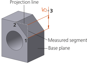
After indication of reference objects and the base plane, a phantom of dimension will appear in the graphic region. The segment being measured is displayed with a dash-and-dot line with two points. Its ends are snap points of the dimension (exit points of leader lines). The hatched line displays the projection line of one of the objects onto the plane of labeling the dimension (the need of projection is determined by the mutual position of objects and the planes for labeling a dimension).
|
The measured segment and projection line are displayed, if in the dialog for setting up the dimensions and designations display, the Connecting lines option is enabled. |
3.Set up dimension text options. To that end, click in the Text field on the Parameter Panel, or press any of the alphanumeric keys on the keyboard. This will start the Add Text subprocess, and the graphic region will display the label entry table and an additional Parameter Panel. Setup is performed in the same way as it is on creation of a dimension in the graphic document. Details...
4.Set the number of decimal places in the dimension text. That is done the same way as during creation of dimension in the graphic document. Details...
5.Set a dimension tolerance. The order of assigning a tolerance is the same as on creation of a dimension in the graphic document. Details...
6.Specify the placement option for the dimension text using the Text Location group of buttons. Setting up the position of a label is performed in the same way as on creation of a dimension in the graphic dimension, with the only difference: on placement of a label on the landing, the landing can’t be rotated using the <Ctrl> key. Details...
7.Set up the drawing dimension arrows.
8.Specify the option of arrangement for the dimension text relative to the dimensional line by pressing the required button in the Text Location group:
 Parallel, above line,
 Parallel, in line break,
 Horizontally, in the line break.
9.If necessary, create a gap between the leader line and the snap point of dimension – in the same way as on creation of a dimension in the graphic document. Details...
10.If necessary, set the name and color of dimension using the elements of the Properties section. More about managing object colors...
11.Set position of the dimension line and text.
•If automatic, fixed, or manual placement of the dimension text is selected, then the specified position of the dimensional line also determines the text location (Fig. a). After indication of this position, creation of the dimension completes automatically.
•If placement of a dimension text on the landing is selected, then the specified position of the dimensional line also determines the origin of the leader line. In this case, it is necessary to set position of the landing (Fig. b). After indication of the landing position, creation of a dimension completes automatically.
12.To complete operation of the command, click Finish  .
.
|
|
a) |
b) |
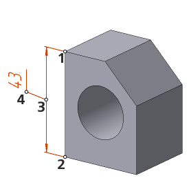
Linear Dimension:
a) without leader landing, b) on the landing
See Also
General information. Controlling and informational dimensions in the model