|
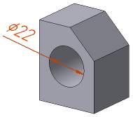
Diameter Dimension |
Scroll |
To set the diametrical dimension in a three-dimensional model, use the Diameter Dimension  command.

Step-by-step instructions
1.Select an object for dimension. Its name will appear in the Object field on the Parameter Panel. A phantom of dimension will appear in the graphic region.
2.After indication of an object, the position of the base plane is detected automatically.
On selection of a flat curve, the dimension is labeled in the plane running through this curve. If the dimension is labeled to the rotational surface face, the position of the base plane can be changed. Details...
3.Select the type of dimensional line pressing the required button in the Type group:
 No Break — the entire dimension line is displayed,
 Trimmed — the dimension line extends from the center of the measured circle to a distance equal to 1/5 of its radius, but not less than the distance specified in the document for the dimension line to extend beyond the text.
4.Set up dimension text options. To that end, click in the Text field on the Parameter Panel, or press any of the alphanumeric keys on the keyboard. This will start the Add Text subprocess, and the graphic region will display the label entry table and an additional Parameter Panel. Setup is performed in the same way as it is on creation of a dimension in the graphic document. Details...
|
If the object to set the diameter dimension is a cosmetic thread, the dimension text is formed automatically. It contains the text of the specified thread designation. If necessary you can edit the caption by means of the Add Text subprocess. |

5.Set the number of decimal places in the dimension text. That is done the same way as during creation of dimension in the graphic document. Details...
6.Set a dimension tolerance. The order of assigning a tolerance is the same as on creation of a dimension in the graphic document. Details...
7.Specify the placement option for the dimension text using the Text Location group of buttons. Setting up the position of a label is performed in the same way as on creation of a dimension in the graphic dimension, with the only difference: on placement of a label on the landing, the landing can’t be rotated using the <Ctrl> key. Details...
8.Set up the Drawing Dimension Arrows.
9.Specify the option of arrangement for the dimension text relative to the dimensional line by pressing the required button in the Text Location group:
 Parallel, above line,
 Parallel, in line break,
 Horizontally, in the line break.
10.If necessary, create a gap between the leader line and the snap point of dimension – in the same way as on creation of a dimension in the graphic document. Details...
11.If necessary, set the name and color of dimension using the elements of the Properties sector. More about managing object colors...
12.Set position of the dimensional line. After that, creation of the dimension completes automatically.
The specified position of the dimensional line also determines the position of dimension text (if the automatic, fixed or manual placement of a label is selected) or the start of the landing (if placement of label on the landing is selected).
13.To complete operation of the command, click Finish  .
.
|
Diameter Dimension
See Also
General information. Controlling and informational dimensions in the model