|
Centerlines created automatically |
Scroll |
The centerlines created automatically are generated in the associative view if the option Objects is enabled in the section Objects under the list Centerlines when setting up view parameters.
Centerlines are created for projections of the revolution surfaces (including simple and threaded holes), axes of which are not perpendicular to the plane of the view projections. If the axis of the revolution surface is perpendicular to the plane of the view projections, no centerline is created for it. When such surface is projected to a full circle, a designation of center is created.
For the revolution surfaces (such as holes) that are not visible in this view, centerlines are created if the display of invisible contour lines is enabled in the view.
Some revolution surfaces do not need centerlines, so no centerlines are created for them. Such surfaces include:
•fillet surfaces that are created using the Filletcommand,
•surfaces of bends in a sheet solid.
|
Centerlines are not created for revolution surfaces in standard parts. If necessary, they can be constructed manually using the command Auto Centerline or Centerline by Two Points. |

You can edit centerlines created automatically. To do this, select the line with a mouse click and set new parameter values on the Parameter Panels and/or change its length by moving the defining points.
|
You can edit centerlines using the defining points in any associative views except the leader element and the node. In the detail view, you can move only those defining points of the centerline that are inside the contour around the view. |
Deleting and restoring centerlines
•To delete all automatically created centerlines of the associative view, Run configuration of the view parameters and disable the Objects option in the Create - Designations in the drawing section of the Objects list.
If you need to restore all centerlines later, enable the option Objects again.
•To delete one of the centerlines, select it and press <Delete>.
Later you can manually create one or more centerlines using the Auto Centerline. This command allows you to create centerlines by specifying objects, as well as Centerlines of projections of faces that have the form of revolution surfaces.
You can re-create all centerlines of the view, if needed. To that end, launch the view parameters setup, disable the Objects option in the Create list — Symbols in the drawing section Objects, and confirm the operation. Then enter the parameters setup again, enable the option Objects and confirm the operation.
Arc centerlines
When projecting a toroidal surface which is obtained by rotating the circle at an angle less than 360°, a centerline is created that coincides with the projection of the guiding circle of the torus.
Depending on the slope angle of the equatorial plane of the torus to the projection plane, the centerline can have the form of a circular or elliptical arc, see the Figure. If these planes are perpendicular, a straight centerline is created.
|
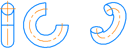
Centerlines: in the front view – a straight line, in the left-side view – a circular arc,
on an isometric projection — elliptical arc
|
If the toroidal surface is formed by a 360° rotation of a circle, a centerline in the form of a circle will not be created. In case the equatorial plane of the torus and the plane of view projections are parallel, the center mark is created, and in all other cases the projection of the torus rotation axis is created (i.e. a straight centerline). |
See Also