|
Constructing spline, broken line, Bezier curve |
Scroll |
In KOMPAS-3D, you can plot:
These objects are constructed by specifying points in the graphics area or by specifying their coordinates. The coordinates of the points, as well as their other parameters, are displayed in the Point parameters table. You can import data into the table from an external file or export the data from the table to a file. Details...
You can use snaps and geometrical calculator.
|
Commands for creating splines, broken lines, Bezier curves are combined into a group. While executing a group command, you can switch to execution of another one using buttons of the Parameter Toolbar header. You can also transfer any parameters you’ve specified between the commands of a group. More information about parameters propagation... |

To construct a spline that passes through the specified points, use Spline by points  command.

Step-by-step instructions
1.Using the group of buttons Method in the Parameter Panel, select the method of internal parameterization of the curve:
 Linear,
 By chord distance,
 Centripetal.
The selected method affects the shape of the curve (see figure).
|
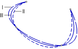
Splines with different methods of internal parameterization
I – Linear, II – By chord distance, III – Centripetal
2.Specify the points through which the spline should pass.
When specifying points, you can view their coordinates using the elements of the Vertices group: the coordinates of the specified vertex in the current coordinate system are shown in the Coordinates field, while the coordinates of already defined points – in Point parameters table.
A phantom of the spline with current settings is displayed in the graphic area.
3.Please select the spline plotting type: closed or open. To do that, use the Close Curve setting.
4.If you want to change the configuration of the spline, go into editing mode. In this mode you can:
•move or delete the points, create points in the existing segments of the spline,
modify the position of the points,
•change the shape of the spline in points, controlling the parameters of tangent vectors and curvature.
After making changes, you can continue specifying points by returning to mode Creation.
5.If necessary, select the style of the spline to be created. More about selecting line style...
6.To complete creating the spline, click Create object  .
.
7.To complete operation of the command, click Finish  .
.
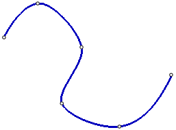
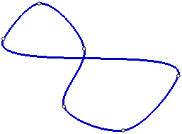
|
|
a) |
b) |

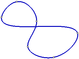
Spline: a) open, b) closed
To plot a spline by poles, you need to set the vertices of its characteristic broken line. The number of vertices is determined by the spline degree.
Boundary points of the spline coincide with the terminal vertices of the broken line; the first and the last segments of the broken line are tangential to the spline in the start and in the end points, respectively. Other vertices of a broken line are the poles of the spline. The points of the spline do not coincide with the poles, but are located at some distance from them. This distance depends on the weight of each pole.
The spline order can take values in the range from 2 to 10; and the weight — in the range from 0.0001 to 999. Fore more details on spline degree and point weight, see Section Spline curves and surfaces. Order of curves. Weight of the points Add-Ons Curves and Surfaces.
To plot spline by poles, use the Spline by Poles  command.
Step-by-step instructions
1.Set the spline degree by entering its value in the Curve order field. You can enter the value manually or select it from the list.
2.Specify the vertices of the defined broken line.
When specifying vertices, you can view their coordinates using the elements of the Vertices group: the coordinates of the specified vertex in the current coordinate system are shown in the Coordinates field, and the coordinates of already defined vertices are displayed in the Point parameters table.
A phantom of the spline with current settings is displayed in the graphic area.
3.The field Point weight allows you to set the weight of each specified vertex of the broken line. Weight can be set before specifying a vertex or after editing vertex parameters (see below).
4.Please select the spline plotting type: closed or open. To do that, use the Close Curve setting.
5.If you want to change the configuration of the spline, go into editing mode. In this mode, the following actions are available:
•change the position of the vertices of the defined broken line or delete them, create vertices on the existing links of the broken line,
modify the position of the points,
•change the weight of any vertex – to do this, select the vertex and enter the desired weight value in the field Point Weight.
After making changes, you can continue specifying broken line vertices by returning to Creation mode.
6.If necessary, select the style of the spline to be created. More about selecting line style...
7.To complete creating the spline, click Create object .
8.To complete operation of the command, click Finish .
|
|
a) |
b) |
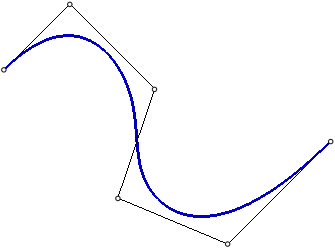
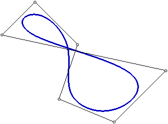
Spline by poles: a) open, b) closed
To build a broken line, use the Broken Line  .
.
Step-by-step instructions
1.Specify the vertices of the broken line.
When specifying vertices, you can view their coordinates using elements of the group Vertices: the coordinates of the specified vertex in the current coordinate system are shown in the field Coordinates, while the coordinates of already defined vertices – in the Point parameters table.
A phantom of the broken line with current settings is displayed in the graphic area.
2.Select the plotting option for a broken line: closed or open. To do that, use the Close Curve setting.
3.If you need to edit the broken line, please switch to the editing mode. In this mode, you can change the position of the vertices or delete them, create vertices on the existing segments of the broken line,
modify the position of the points,
After making changes, you can continue specifying vertices by returning to mode Creation.
4.If necessary, select the style of the broken line to be created. More about line style selection...
5.To complete creating the broken line, click Create object .
6.To complete operation of the command, click Finish .
The constructed broken line is a single drawing object, it will be selected, edited and deleted entirely.
|
|
a) |
b) |
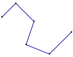
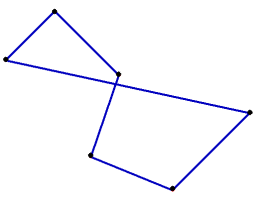
Broken line: a) open, b) closed
Notes on constructing a broken line in a sketch
To build a Bezier curve, use the Bezier Curve  command.
Step-by-step instructions
1.Specify the points through which the curve should pass.
When specifying points, you can view their coordinates using group of elements Vertices: the coordinates of the specified point in the current coordinate system are shown in the field Coordinates, while the coordinates of the already defined points are displayed in Point parameters table.
The graphic area displays a curve phantom with the current settings.
2.Select the curve construction option – closed or open. To do that, use the Close Curve setting.
3.If you want to change the configuration of the curve, go into editing mode. In this mode, the following actions are available:
•change the position of points or delete them, create points on existing parts of the curve,
modify the position of the points,
•change the shape of the curve, controlling the length and direction of the tangent vectors/
After making changes, you can continue specifying points by returning to mode Creation.
4.If necessary, select the style of the curve to be created. More about line style selection...
5.To complete the build, click Create object .
6.To complete operation of the command, click Finish .
|
|
a) |
b) |
Bezier curve: a) open, b) closed