|
Structure of the Design Tree and Working with its Objects |
Scroll |
Design Tree Structure
The root element of the Design Tree is the model itself, i.e., a part or an assembly. The composition of the information displayed in the root element row is customizable (see sections Name format in Document Tree and Root control).
Icons and names of model objects are automatically displayed in the Design Tree immediately after these objects are created (see section Names and icons of objects in the Tree).
Components of an assembly model — parts and subassemblies — are separate models. Therefore, component objects are located in the corresponding Tree branches.
The Tree contains additional information about the model shown as icons in the left-hand part of the Tree and icons in front of object names.
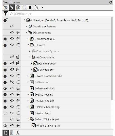
Assembly Design Tree
Working with Objects of the Design Tree
•The general working methods are described in section Using the Document Tree.
•Search for objects in the Tree is described in section Search in the Document Tree.
•Changing the building sequence (available if display of the Design History) is described in section Changing the operations sequence.
•Selection and designation of objects in the Tree is described in section Selecting objects in the Design Tree.
•Sorting of components and bodies in the Tree is described in section Sorting objects in the Design Tree.
•Work with variables of a selected object is described in section Working with variables in the Model design tree.
•You can control objects using icons or context menus.
•Icons are displayed in the fields in the left part of the Tree (see Figure). They let you to configure objects separately. When you move the cursor to an icon, a shortcut with the name of the current property value appears. Clicking the icon changes the property value to the opposite (if there are two values), or opens up a list of values (see Figure). The list of properties and, respectively, icons, depends on the type of object, for example:

 — visible/hidden object (about visibility control, see section Controlling visibility of individual objects),

 — an object included in the calculation/excluded from the calculation (for exclusion from the calculation, see section Excluding objects from calculation).
You can configure a set of fields with icons. To do that, use the menu invoked by the  button in the Tree header. For example, when working with assemblies you can enable display of the field showing the load type of the assembly and its components.
•Right click the selected object of the Tree to open context menus. Context menus allow you to configure objects both separately and in groups (to do this, before running a command, select all the objects to which it is to be applied). The context menu contains not only commands to change the properties but also other commands to control objects; see Figure.
|
|
a) |
b) |
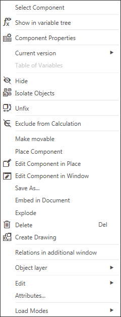
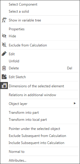
Context menu of objects in the Design Tree
a) of a component, b) of an operation
|
All commands in the context menu of sections, except for the Attributes command, apply to all objects included in this section. |
