|
Creating BOM Items |
Scroll |
This section first outlines the step-by-step instructions for creating a BOM item and an external BOM item, and then describes the features of this process for various cases.
General procedure for creating a BOM item
1.Run the required Add BOM object  command or External BOM item
  .
.
BOM items can be created in the drawing and assembly, and the external items can be created in the assembly, part, and fragment.

2.In the dialog that appears on the screen select a section for placing the item, and a template for filling its text part (if required).
3.Click Apply.
The BOM object window (see figure) containing a fragment of the BOM table: the table header and one row, appears on the screen. The table corresponds to the BOM style included in the current BOM description.
When creating an external BOM item, the values of the corresponding properties of the product are displayed in the Designation and Name columns.
|
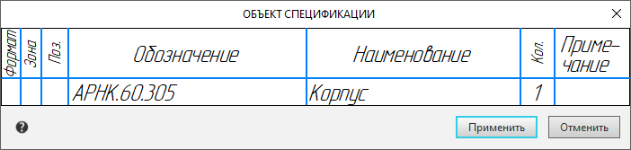
The window for entering the text part of the BOM item
Elements appear on the Parameter Toolbar for setting the parameters of the item and its text.
4.In the BOM object window, enter or edit the textual part of BOM item.
5.If the object being created should not be included in the BOM, the style of which is included in the current description, uncheck the Apply in current BOM description option in the Parameters Panel. Details...
6.If required, fill in the additional columns and attach documents to the item..
7.Confirm the creation of the specification object by clicking the BOM object button in the window, or the Apply button, or the Create Object  button on the Parameter Panel, or by pressing the <Ctrl>+<Enter> keys.
Notes on creation of BOM items
•There can be several BOM items in a document, and only one external item.
Therefore, when the External BOM object command is called again, a filled window appears, i.e., it is proposed to edit the previously specified properties of the item, whereas when the Add BOM object command is called again, an empty window appears, i.e., data input for a new object is expected.
The BOM items available in the document can be viewed and edited in the subordinate mode of working with BOM items, and to view and edit an external BOM object, use the External BOM Object command.
•The name of the BOM section specified when creating an external BOM item becomes the value of the BOM section field. You can view and edit the specified value using the Properties command, enabling the display of the BOM Section property in the list of properties.
•When creating a BOM item in a drawing, you can pre–select the graphic items (including the positional leader line) that will become the geometry of the created BOM item.
In this case, it is convenient to invoke the Add BOM object command from the context menu of the selected objects.
If required, graphic objects can be included in the geometry of the BOM object or exclude from it later.
•Unlike in the drawing, positional leader lines in the assembly do not need to be included in the geometry of the relevant BOM objects. They are included in the geometry of the corresponding items automatically. Details...
•Objects with properties (components and solids in the assembly, macro-elements in the drawing, inserts of fragments and types) are always included in the geometry of BOM items that are automatically created based on the properties of these items. You can’t delete them, but if required you can include them in other BOM items (and delete from other BOM objects).
•To the external specification object in the model, all automatically connected to it documents, as well as documents, connected to the model on the Product Composition Panelare automatically connected.