|
Product BOM in a graphic document |
Scroll |
When working with graphic documents, the Product BOM panel (see Figure) is available. The features it offers are generally similar to the features when working with models, but they have some constraints. For more details, these options and constraints are described below.
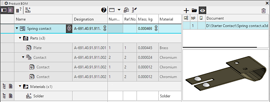
Product BOM panel in the drawing with assembly associative view
Including the Product BOM panel in a graphic document is done using the Product BOM button  in the button block near the left border of the <%PRODUCT_NAME%.> window. If the block has no such button, invoke the Settings — Toolbars — Product BOM command.
Areas and controls of the Product BOM panel when working with a graphic document are basically the same as while working with the model. As for the model, you can configure the table displayed on the Panel: enable/disable columns, change their order, etc..
On the Product BOM panel, when working with a drawing, the properties of the drawing itself, properties of the macro-elements contained within it, fragment inserts and view inserts from other drawings, as well as the properties of the BOM items, created manually are displayed. For an associative drawing, the Product BOM panel also displays the properties of the BOM items of the model projected into it. If a drawing contains projections of several models, the Product BOM panel displays data only about one model — the one from which the drawing is created, which values of the properties are transferred from and BOM data ( If getting BOM data from the model is disabled, then information about constituent parts will not be available in the associative drawing and cannot be displayed on the Product BOM panel.
|
By default, macro-elements, inserts of fragments, and types are excluded from the product BOM, i.e. they will not be displayed in the BOMs created from the drawing. If necessary, you can include them in the product BOM. |

When working with a fragment, the Product BOM panel displays the properties of the fragment itself, as well as the properties of macro-elements and inserts of other fragments. The creation of constituent parts manually in the fragment is not provided for.
The constituent parts on the Product BOM panel are arranged into sections and sorted according to the current BOM style, and the same constituent parts are grouped. More information about sorting and grouping of consistuent parts...
Establishing property values
Inputting the property values on the Product BOM panel in the drawing is done in the same way as in a model.
The exceptions are the following:
•The property cell Material has an icon  , a click on which invokes a menu with commands for selecting a material from the list and from the reference book. The density of the selected material becomes the property value Density. Additionally, to the properties of Material and Density, as well as the property of Mass, you can assign any arbitrary values by entering them from the keyboard.
•Changed property values cannot be send to the source.
•When assigning the value of the property Name, input of additional data is not available.
The values of some properties cannot be assign – their cells have a gray color. For example, in graphic documents, it is not possible to assign the property value Dissect at cuts, and in a document of type drawing, it is not possible to set the property value BOM section.
The values of properties of constituent parts projected into the drawing cannot be edited.
As with working with a model, identical constituent parts merge into a group and displayed as a single (group) string. Changing the value of the properties in this line will be transferred to all constituent parts of the group. If the group includes non-editable constituent part, i.e. those belonging to a projected assembly in a drawing, then:
•The values assigned into the grouping row are transferred only to those constituent parts whose properties can be edited, except for the Position property: it will be changed for the constituent part of the projected assembly as well.
•The property value Quantity in the grouped row is not available for editing (it is always calculated automatically).
Creation and deletion of constituent part
In the drawing, you can manually create new constituent part, i.e., objects that represent sets of properties. As when working with the assembly, to do this, use the command Add to product  on the Product BOM panel.
It is possible to delete constituent part, which were created manually, from the drawing using the command. Delete  on the Product BOM panel. In addition, it is possible to delete constituent part corresponding to macro-elements, inserts of fragments and views. It's essential that deleting constituent part with a visual representation also removes the associated images, which are connected to the constituent part (i.e., macro-elements or fragment/views inserts).
You can't delete the constituent part projected into the drawing from this drawing. You can disable creation of these objects in drawing.
Reference number placement
When working with the drawing, it is possible to automatically assign position numbers on the Product BOM panel, i.e., the calculation of the property values Position for the constituent parts. Position numbers are assigned using the Set ref.Nos.  command on the Product BOM panel. Conditions for the availability and the procedure for executing the command in the drawing are the same as in the assembly.
If the calculated positions in the drawing for the constituent parts of the projected assembly differ from the current positions of these components, their positions are adjusted according to the calculation (despite the fact that manual changes to the property values of such constituent parts are not possible).
Working with documents
To display the area for working with documents linked to the product and its constituent parts on the Product BOM panel, press the Documents button  . In general, the same features are available as in a model: (view already connected documents, add and delete documents), with the following features and constraints:
•Documents related to the entire product:
You can connect and disconnect any documents to the entire product (i.e., to the object located in the very first row of the table). Among other things, it is possible to disconnect the model and other documents automatically added to the list of items connected to the product as a result of creating associative views in the drawing. The difference from working with documents in a model is that it is not possible to get the value of the Format property from documents attached to the item.
Typically, the BOM for a product needs to be connected to its assembly drawing, while documents related to the image contained in the fragment should be connected to the fragment (these documents can be quickly accessed when working with another document into which the fragment will be inserted).
•Documents attached to constituent parts of products:
•If the constituent part is created manually, it has the same capabilities for working with documents as in the model for constituent parts without visual representation, i.e., adding and deleting documents, as well as selecting documents to extract properties from them,
•If a constituent part corresponds to a macro-element or a fragment/view insert, it has the same document handling capabilities as in the model for constituent parts corresponding to components, i.e., adding and deletion documents (except those connected in the insert source), as well as selecting a document to extract its Format properties.
•If a constituent part belongs to an assembly projected into a drawing, neither adding documents to the list of linked documents nor deleting documents from this list is possible.
Working with blanks
In the drawing, you can manually add blanks for any BOM items (including those belonging to the assembly projected into the drawing) and work with them just as in a model.
If the assembly projected in the drawing has components with blank models, then only viewing is possible for such blanks.
The Product BOM panel can be switched to a special mode for working with versions by pressing the Performance mode button  . This button is available if the Product BOM panel is displayed in expanded view and if the number of versions of the item for which the drawing is issued is greater than one. The number of product versions is displayed in the Number of versions for group documents field of the dialog. Descriptions of BOMs and exceeds 1 in the following cases:
•In the drawing, a model having multiple versions has been projected,
•in the descriptions of BOMs a drawing has at least one description containing a group BOM style.
In the performance mode on the Product BOM panel, the constituent parts included in all versions of the product are listed, and the Quantity property column is displayed divided into several columns (their number is equal to the number of the product versions). Thus, you can view and edit the properties of all constituent parts simultaneously, including the quantity of each constituent part for each version. If necessary, using the list to the right of the Performance mode button , you can select the versions for which the columns for inputting the quantity will be displayed.
For the constituent parts belonging to the assembly projected into the drawing, in the execution mode, as well as in the regular mode, only previewing the property values is available.
|
The number of versions may exceed 1 even if the drawing lacks a description with a BOM group style. The thing is that the number of versions is a characteristic of the entire product, therefore, after the description with a group style is removed from the document, the number of versions does not automatically become equal to one (but becomes unavailable for editing). Thanks to this, the quantities of components for all versions are preserved in the document, if they were specified. You can view and edit them on the Product BOM panel in execution mode. |
Advanced options
Additional functionalities for working with constituent parts are available in the context menu, which can be invoked in the columns Name and Designation of the table on the Product BOM panel.
•For the constituent parts belonging to the projected assembly, only the Edit in window command is available, allowing to open the corresponding model in a separate tab.
•For the remaining components and the entire product , the following commands are available:
•Properties — allows you to proceed to editing properties of the product or its component. To learn about working with properties, see sections Properties of a drawing/fragment, view/fragment insertion, macro-element.
•Select from reference — allows you to select a designation of a product or its component part from the external reference ( United System of Design Documentation). The reference should be connected to KOMPAS-3D.
•Show in tree — for views/fragments and macro-elements insertions allows to find the constituent part in the Model tree. The object for which the command was run is highlighted in the Tree. If necessary, it expands the required section of the Tree and opens automatically to make the highlighted row visible.
•Edit source — allows to proceed to editing the source image of the constituent part. The command is present in the menu if the constituent part represents:
•fragment or view, inserted by reference — the command opens a fragment or drawing file that is the source of the insertion,
•fragment, inserted by embedding This command opens the fragment inserted into the current document for editing.